Thank you so much for this. Since 2 years I am searching for this, i knew it was something easy. I had problems with the control pod since I puchased this system, finally i can thow it into the trash bag where it belongs to. Unfortunately my electricity comes from an solar inverter with a sharp sinus curve and i have heavy humming since it's now on 100% volume. you know if there is a way to get the poti back in?
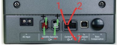
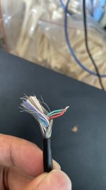
For everyone else going for this mod and you still have the control pod, cut the cable in half. The colors of the cables are:
1 = Red
2 = Green
7 = Gray
connect all 3 cables together and plug in the connector, done!
I think purple and orange is for left and right input.
Thanks again, i was about to throw it away.......
Hello Guys,
I made a video on YouTube about turning on the subwoofer unit with the control pod.
I hope this can help you using the multimedia speakers system without the control pod.
Thanks
Would you re-up video plz!
Thanks
Thank you so much for this. Since 2 years I am searching for this, i knew it was something easy. I had problems with the control pod since I puchased this system, finally i can thow it into the trash bag where it belongs to. Unfortunately my electricity comes from an solar inverter with a sharp sinus curve and i have heavy humming since it's now on 100% volume. you know if there is a way to get the poti back in?
For everyone else going for this mod and you still have the control pod, cut the cable in half. The colors of the cables are:
1 = Red
2 = Green
7 = Gray
connect all 3 cables together and plug in the connector, done!
I think purple and orange is for left and right input.
Thanks again, i was about to throw it away.......
Hello, did it correct ? but no sound, when i move this cord few sound happen.
Attachments
No need to modify the Pod connector, only modification of the AC power cord needed. see the attached image.Would you re-up video plz!
Thanks
The advantage of this modification is that when the computer is shut down, the AC power supply is cut off. When the computer is turned on, the Companion 5 will automatically produce sound and not remain muted.
Attachments
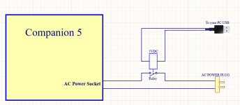

No control pod needed at all. follow the steps below:
1) Do not plug the control pod.
2) Power on your computer first. Once the computer is turned on,
3) plug in the AC power supply for the Companion 5.
4) Now you should be able to hear the sound.
My modification is to not manually turn on the AC power supply for Companion 5, using a relay to turn on Companion 5automaticly.
Hello Guys and Girls,
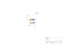
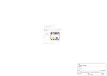
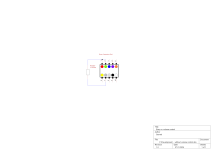
I had the same problem as you, and my control pod for the Bose Companion 5 failed. I took it upon myself to create a schematic and build a replacement. Just a disclaimer: I'm not an electronics technician, so please take it with a grain of salt. With some videos, this thread, and a lot of time for reverse engineering, it pointed me in the right direction. This is a detailed explanation for those who have not much experience with electronics.
To describe the schematic, it's from the point of view looking from the back onto the subwoofer, meaning the notch would be on the top of the schematic. Pin numbering is from top left to top right, then bottom left to bottom right. The colors in the schematic represent the colors of the strands in the cable of the control pod. I am aware that there are multiple versions of the Companion 5 based on the country. I'm not sure if this will align with your version. Just so you know, mine is from Germany.
I have prepared 3 versions, getting more complex but adding more functionality.
I hope I could help anyone with this explanation. Good luck repairing!
TL;DR: If you are knowledgeable, use the schematic and use a 220uF, not 22uF, just to be sure. I did not connect the audio out; only audio in works.
I had the same problem as you, and my control pod for the Bose Companion 5 failed. I took it upon myself to create a schematic and build a replacement. Just a disclaimer: I'm not an electronics technician, so please take it with a grain of salt. With some videos, this thread, and a lot of time for reverse engineering, it pointed me in the right direction. This is a detailed explanation for those who have not much experience with electronics.
To describe the schematic, it's from the point of view looking from the back onto the subwoofer, meaning the notch would be on the top of the schematic. Pin numbering is from top left to top right, then bottom left to bottom right. The colors in the schematic represent the colors of the strands in the cable of the control pod. I am aware that there are multiple versions of the Companion 5 based on the country. I'm not sure if this will align with your version. Just so you know, mine is from Germany.
I have prepared 3 versions, getting more complex but adding more functionality.
1. Without volume control (see schematic below)
This version will pull up the volume to 100%! As written here in the forum, I connected the Red (Pin 1, top left looking at the subwoofer), Green (Pin 2), and Grey (Pin 7) together. This results in heavy humming, as user "scheissegalo" describes. To remove this clicking/humming noise, I added a 10KiloOhm resistor between the Grey (Pin 7) cable and the others. If you get no sound, please continue reading; I will come to the state of the control pod later.
2. Volume controlled (see schematic below)
To add volume control, you can use a potentiometer (variable resistor) between Red (Pin 1) and the others. What will happen is: power from Green (Pin 2) around 10-12V will split to Red (Pin 1) and Grey (Pin 7). Grey (Pin 7) is ground, and Red (Pin 1) is connected to something like a capacitor. The voltage at the capacitor determines the volume. The highest volume (100%) is reached if the potentiometer has a resistance of 0, then the voltage of Green (Pin 2) is the same as at Red (Pin 1). To reduce the voltage and thereby the volume, we increase the resistance of the potentiometer. More of the voltage will then drain to ground, but not all of it. Even if the resistance of the potentiometer would be very high, some voltage would leak through. To compromise, I would recommend adding a 100KOhm resistor. Then, if the resistance is high (100KOhm), the volume will be 10Kohm / 100KOhm = 1/10 -> 10% of maximum volume, which is enough in my opinion. You can also mute the audio system (see 3).
Two things to be aware of:
* Potentiometers don't like heat and are easily destroyed by soldering; be quick.
* Behind Red (Pin 1) is a capacitor that results in the audio not being instantaneously changed. The capacitor is slowly charged and discharged, so the volume lags behind the input, something like a second. Don't blow your ears off ;-)
3. Replacement
This will not get the audio out line for headphones working! I did not need that functionality. I only wanted to use the Aux/Audio In. It starts from 2) and adds a mute functionality by adding a switch between the 10K resistor and Grey (Pin 7). If the connection is severed, the volume will go down to 0% (turn down the volume before using this functionality). To add the aux-in, follow the schematic. Add the tip of the Aux cable (Left Channel signal) to violet (Pin 4), the ring (Right channel signal) to orange (Pin 5), and finally, the shell (Ground) to black (Pin 9).
Finally, to get to the state of the audio system, probably the error the user "yuchiro" encountered. If you connect the USB cable to a PC or similar device, the system will be in the USB state and will not be controlled by the Pod. To enable Pod control, we need to switch the state. To do this, black (Pin 9) and white (Pin 10) need to be connected when the audio system is connected to power. After a little while (I don't know how long), the connection needs to be severed to get into Pod control mode. To achieve this, I used a capacitor between those pins. While the capacitor is charging, it allows current to flow; when the capacitor is fully charged, the flow stops, and it behaves like there is no connection. I used 22uF (22 microfarad), but bigger is better, more like 220uF. As of now, with 22uF, I sometimes plug the audio system in twice to get it to the right state. The direction of the capacitor is important; minus should go to black (Pin 9).
I hope I could help anyone with this explanation. Good luck repairing!
TL;DR: If you are knowledgeable, use the schematic and use a 220uF, not 22uF, just to be sure. I did not connect the audio out; only audio in works.
Attachments
- Home
- Source & Line
- PC Based
- How to bypass Bose companion 5 control pod using USB Cable