Are you sure each of the two secondary windings has one blue AND one green wire? (and how do you know which is which?) Have you tried with only one secondary at a time?
If STS9fan's transformer is an Antek, or color coded like one, the secondary pairs do use one blue and one green for each secondary winding. Best way to check if you have a "pair" from the same winding, is to use an ohmmeter during construction to identify each pair, or to measure the secondary winding voltages (carefully) with power applied (carefully). (This is what I'm asking STS9 to try.....and also to check the rectifier bridges (for unfiltered DC), as well as the cap banks (for opens/shorts).
please remember to discharge supply caps, before 'messing' with connections
discharge with a large wattage resistor
Tinitus, good point. I think I see bleeder resistors across the first caps of the CRC filter (although I can't read their values). Hopefully, they are sufficient (although an unloaded F5 PSU can take some time to discharge--my LED PSU status lights tend to say on for 10 seconds or so, after I remove power)
As a practice, I always use bleeders across PSU caps. In addition, after a suitable discharge period, I will also "short" my meter leads across the capacitor, before I try to take any resistance measurements--need to do so, to get accurate measurements, and to protect my el cheapo Harbor Freight DMM's
 from self-destruction....
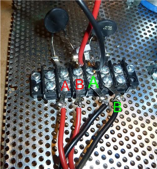
a sheet of sticky back plastic would be better than nothing. One side will be mechanically held down by the fitting. Can the other side be mechanically held down with non conductive fittings?I will take all those readings and report back. It is an antek so I think that is correct. Also I am pretty sure yhe CL60s are one on each primary. As far as insulation goes I can get something under there. Would nylon standoffs be ok?
6L6: You mean "primaries," not "secondaries....
Quite.
Good catch!
Fixed!!! ...I had my secondarys mixed. Everything looks great now. Thanks everyone!
Did you have your primaries mixed up? The Red/Black ones connected to the black barrier strip with the thermistors? I said it wrong earlier and now I don't want you repeating...
Or was it the (actual) secondaries, the blue/greens connected to the rectifier blocks?
Anyway, I am glad to hear that it is working! It's great that it's not something expensive, and just a simple wiring mix-up!!!
More photos of your progress, please!!
(As it happens, obviously...) so 6L6 , Jim , is yours done and are you listening to it yet ?
i've got mine finally in my system and enjoying it a lot . playing with speakers now .
sucks when life gets in the way of having fun , but mine's been really hectic (daughter's going to college stuff ) . thank god i've got my escapes like building amps and motorcycles
cheers , Woody
i've got mine finally in my system and enjoying it a lot . playing with speakers now .
sucks when life gets in the way of having fun , but mine's been really hectic (daughter's going to college stuff ) . thank god i've got my escapes like building amps and motorcycles
cheers , Woody
Na it was the secondarys. I had the wrong green with the wrong blue. Anyway I should have it together pretty fast now. I will post pictures.
Easy mistake to have made. Fortunately, I had some kind soul describe to me how to match them when I initially built mine. Glad its running smooth now!
Russellc
Na it was the secondarys. I had the wrong green with the wrong blue. Anyway I should have it together pretty fast now. I will post pictures.
Well done..... That's why I asked you to measure the secondary winding AC voltages going into the bridge, as well as the unfiltered DC outputs from the bridge. Considering the output voltages you were quoting, this was the best candidate for "probable cause". Measuring those secondary voltages (or measuring the resistance of the secondary windings, without power applied) should have quickly isolate this one.....
For my curiousity, do you have measurements on your two "rail voltages" (+ power supply output to ground, and - power supply output to ground)? Without a load, you should be reading 25.0~25.3 volts..... for each rail.
Again, congrats......
so 6L6 , Jim , is yours done and are you listening to it yet ?
Yes! I guess I never really said that, did I...
It's fantastic! I know it will be in my collection for a long, long time. I have really enjoyed the project, it went together quite easily, even if it the assembly was spread out over a very long time -- I don't have a dedicated space, and I had to drag everything out, do a little work, and then pack it all up again, all while my toddler was taking his morning nap...
I'm kinda in a DIY-a-thon right now, (bummer, huh...) and I have another project to get done, as my Wife has requested an amp with a smaller footprint for the upstairs system. The very Hi-Fi looking, huge chassis F5 is very big in it's current location... I have this neat chassis/frame from an old tube Tectronics module, and it will become a Peter Daniel chipamp. I need but the transformer and Kit, the rest I have at hand. It feels really good to put to use a bunch of stuff from my junkboxes, things that I have been collecting for a long time now.
Instead of the IXYS, use discrete diodes - I genrally use the Isolated tab Phillips BYW series but the 8ETH06s are possible cleaner
Hi James,
I was looking at the BYW and 8ETH06 diodes and they are rated at 8A. Is this sufficient for the F5?
Hi James,
I was looking at the BYW and 8ETH06 diodes and they are rated at 8A. Is this sufficient for the F5?
I wouldn't think so. Inrush current will probably blast 'em.
I'd like to get some of these. Then you don't need to put them in a PC board. Just screw them down.
VBE55-06NO7 Ixys Bridge Rectifiers
- Home
- Amplifiers
- Pass Labs
- How to build the F5