I should pull the protection circuit fuse and measure the current draw. My transformer is rated for.810ma per output. The three large relays should draw half that. There's brown stuff (transformer magic smoke equivalent) running out the bottom. I've replaced the transformer and disconnected the tube transformer relay. This one's running cooler.
My transformer is rated 1A, it's relatively warm, but no "strange" behavior, so I'm kind of fine with that
")
Last edited:
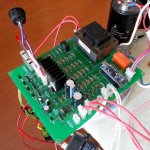
I think I may have damaged my transformer firing the amp up through a 50 watt bulb limiter. All sorts of strange things happened when the inrush relay closed and it blew a 125mA fuse once. I started noticing the "Hot" smell periodically after that. This is pretty much a sacrificial amp. I have extra boards for all parts of it so I'm running every possible scenario I can think of to make sure there's no danger of fire, ect. before I take it home and try it out. The fellow I work for is pretty electronically challenged so I've become accustomed to having to do this.
I think I may have damaged my transformer firing the amp up through a 50 watt bulb limiter. All sorts of strange things happened when the inrush relay closed and it blew a 125mA fuse once. I started noticing the "Hot" smell periodically after that. This is pretty much a sacrificial amp. I have extra boards for all parts of it so I'm running every possible scenario I can think of to make sure there's no danger of fire, ect. before I take it home and try it out. The fellow I work for is pretty electronically challenged so I've become accustomed to having to do this.
Well, in fact this small "standby" transformer powers only the board itself and the relays. So, it's not that easy to damage it, whatever happens with the main amp circuit.
The only thing I suspect - with regards to your smell/smoke - is the inrush resistor. During the period, when the main transformer is connected to mains through this resistor (inrush delay, like 2 seconds), it may be exposed to relatively high currents, especially is something is wrong with the power section. What kind of resistor do you use there?
I have a 50 watt chassis mount 20 ohm power resistor. I'm pretty sure the smell was the transformer cooking. It was definitely damaged. It became too hot to touch within a minute of power up yesterday with only the power and inrush relay connected.
When the fuse popped the transformer was already pretty warm. It had been running for a few hours with all relays on. The inrush of the main transformer was actually causing the protection board to restart so there would have been a couple relays dumping back into it's supply along with inrush from restarting again at the same time so I imagine it was pretty abusive on the poor little standby transformer.
As another possible current saving idea, would there be any issues dropping out the inrush relay after the main power relay engages? I know they don't draw a lot of power. Just kicking ideas around.
That's right. Arduino has got FTDI chip on-board (at the bottom side of PCB - not visible on the picture).
This allows using standard USB interface to access its RX/TX.
There is also set of ICSP pins on the other side, allowing direct access using serial interface.
For me - USB is more than enough (I'm not going to change the boot-loader or something like that
Oh ! so the Arduino is SMD on a dip "breakout" package. This would make
the script accessible on a PC. (I have the software).
What does the reset do ... ?
OS
If someone will supply a schematic for a test and or proof of concept married with a simple amplifier of an OS persuasion. I could make a pcb layout for it without too much trouble. I have a 30 pin Arduino on hand and could build and test it on a solder-less breadboard etc.
A kinda of integration of your great board into a proof of concept board with a real amp on it. Just for testing and yes maybe biasing too. A ALL in one board, more or less.
We've already got it up and running. I'm just kicking around ideas for round 2. It works very well.

We've already got it up and running. I'm just kicking around ideas for round 2. It works very well.
You got a biasing circuit working? Schmo?
Just out of curiosity Valery, how many amps have you used this on? Have you had any issues?
Well, I test every new IPS / OPS or both sections with one of these boards... maybe 12-15 different setups or so in total... including the hybrids.
No issues whatsoever. Very good investment in Arduino
Well, I test every new IPS / OPS or both sections with one of these boards... maybe 12-15 different setups or so in total... including the hybrids.
No issues whatsoever. Very good investment in Arduino
Mine's surviving the torture chamber very well. The only bug so far looks like a faulty resistor and a transformer that's not 'manly' enough.
- Status
- This old topic is closed. If you want to reopen this topic, contact a moderator using the "Report Post" button.
- Home
- Amplifiers
- Solid State
- How to build a 21st century protection board