That sucks. (for my input idea)
I guess the red led will like it .... I'll flash it real bright.
You could of just left em "raw" - 40ma unbuffered (leds) or
"scriptable" input modes with no components.
OS
You could get creative and leave pin 4 or 5 unhooked on the ULN2003. Use the pad for an input. I prefer just to use the 12V trigger.
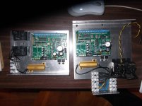
Is there a photo or layout of the new board available? Maybe I missed something...
Photos http://www.diyaudio.com/forums/soli...-century-protection-board-38.html#post4189700
Schematics http://www.diyaudio.com/forums/soli...-century-protection-board-39.html#post4189974
Nice pix , Jeff.
Q6/7 don't have to be heatsinked , do they ? they never even got
warm with the mechanical relays ?
OS
Nice pix , Jeff.
Q6/7 don't have to be heatsinked , do they ? they never even got
warm with the mechanical relays ?
OS
They were just convenient to bolt down there. No need for heat sink.
Don't have any 11k/R24 , there are extra 100k,820k ?
For the 11K/R24 ...that would be the comparator reference. 5/12= .416v
Vbe trip point. Wonder what temp. a MJE340 hits .416 Vbe ?
If I used the 10K for R24 I'd have 5/11=.454 Vbe , which would be a lower
temp.
Or , if I used the 12k (I have it) I'd have a super low ref. of .38V. here you could just
raise the 340 Vbe with resistor in series with it (or a trimmer.).
What value did you use and at what temp does your thermal trip ?
OS
Don't have any 11k/R24 , there are extra 100k,820k ?
For the 11K/R24 ...that would be the comparator reference. 5/12= .416v
Vbe trip point. Wonder what temp. a MJE340 hits .416 Vbe ?
If I used the 10K for R24 I'd have 5/11=.454 Vbe , which would be a lower
temp.
Or , if I used the 12k (I have it) I'd have a super low ref. of .38V. here you could just
raise the 340 Vbe with resistor in series with it (or a trimmer.).
What value did you use and at what temp does your thermal trip ?
OS
I've used 10k and 11k but never checked trip points yet. I've been wanting to put together a chart.
I've used 10k and 11k but never checked trip points yet. I've been wanting to put together a chart.
My last idea of trimming out the vbe would be the safest for 12k.
The extra resistor to ground would be for(lower than) 10k
I just checked a mje340 , .67V at room temp ... boiling water 100C
barely below .57V.
If the comparator trips right at reference it would take R24=8.2K to match
a 100C MJE340 ?? whoa.
2sc3503 is an even higher room temp vbe , don't know about BDxxx.
The r23/27 I source value will also affect Vbe.
OS
What temperature should we be shutting BJTs down at? I was thinking of tripping mine at 75C. I barely passed 65C running sine waves into 4 ohms.
What temperature should we be shutting BJTs down at? I was thinking of tripping mine at 75C. I barely passed 65C running sine waves into 4 ohms.
70C-80C is quite below the data sheet derating max..
I can't get my heatsinks too hot to touch ... (50C+) with the level I have played it
at so far.
Jeff .... you are using those foot long (6" wide) heatsink USA extrusions ??
PS - all 54 resistors are done ... hardest soldering I ever did @ 1mm spacing?
Arrgggg ! Diodes/caps will be so much easier !! Even the smd wont be that bad.
OS
My heatsinks are scrap deHavilland wing molds milled to shape. 16" x 6" x 2".
I think I'm going to get the syringe of low temp solder out for my next one and cook it in the toaster oven. There's a lot of connections on that little board.
Got a big pile (strip of) 1n914's ... any difference (from the 1n4148's) ?
OS
They're fine here. Don't forget about the backwards silk for D4.
They're fine here. Don't forget about the backwards silk for D4.
Whaaaaat !!! Now you tell me. You mean D4 the zener I just installed

Ohh just looked ... that goes to the 3V reg which is the "heart" of this baby.
PS - you pick the best mistakes ... huh ??😀
Just kidding .... but that would of smoked the reg and the ATmega !
os
Last edited:
It keeps it interesting. 😀 That's just a reference for the voltage detector. It would just shut down.Whaaaaat !!! Now you tell me. You mean D4 the zener I just installed
Ohh just looked ... that goes to the 3V reg which is the "heart" of this baby.
PS - you pick the best mistakes ... huh ??😀
Just kidding .... but that would of smoked the reg and the ATmega !
os
Last edited:
It keeps it interesting. 😀 That's just a reference for the voltage detector. It would just shut down.
You had me worried there. later cursing might of followed "It don't #%@@ing work"😀 Awww , no smoke ? (at least you know your" faults").
OS
Getting close...
A question for Jeff -
C2 , decoupling for the CMOS 3V regulator input , does it have to
be 152 (1500pf) could a .01uF work here ??
Also , can the 2n5551 (Q4 or Q5) be just about anything.??
They are zener protected and only see logic levels at output.
BC550 would be reverse pin and mpsa42 would be pin perfect.
Any special quality of the 5551 for this part of the DC detect circuit ?
Want to be perfect with both (below). Designed "anal" control
assemblies for both sub and main amp applications.
Since I only have enough MOSFETS for the main amp SS relay's ,
the sub will be paralleled mechanical's ( good enough).
SS relay PCB's might have to be trimmed down a little (tall) -
I'll have to check when I install.
OS
Attachments
Last edited:
A question for Jeff -
C2 , decoupling for the CMOS 3V regulator input , does it have to
be 152 (1500pf) could a .01uF work here ??
Also , can the 2n5551 (Q4 or Q5) be just about anything.??
They are zener protected and only see logic levels at output.
BC550 would be reverse pin and mpsa42 would be pin perfect.
Any special quality of the 5551 for this part of the DC detect circuit ?
Want to be perfect with both (below). Designed "anal" control
assemblies for both sub an main amp applications.
Since I only have enough MOSFETS for the main amp SS relay's ,
the sub will be paralleled mechanical's ( good enough).
SS relay PCB's might have to be trimmed down a little (tall) -
I'll have to check when I install.
OS
C2 sets the speed of the AC failure detector. I installed 1500pF because it was in front of me at the time. It can likely be much smaller. It just needs to take enough ripple off the half wave rectifier to keep the voltage detector from triggering.
The DC detection circuit is Valery's design but I don't think there's anything special need there.
You can chop the top off the SS relay. The mosfets run stone cold with 400 watt sine waves running through them (I think I did the math right. 40VRMS into 4 ohms?)
Cool. I have 470p (silver) 680p , 1000p for C2.
So thats the AC detect , I thought the ATmega needed another supply.
All it needs is just 5V (Vcc).
Looks like an "update" from the last circuit !! 🙂
I calculated what the opto's will do on overload.
If you go emitter to emitter on a OP stage (.44R) ,
Edit - just short of 4.5W on the .22R's , as well.
Hcpl2530 and the resistors (R 15-18) need 2V to trigger. The 2530's led has a 1.5Vf.
Thats 4.5A/2 = 2.25A per emitter resistor,
On the slewmaster - 11.25A per rail. Am I wrong ?
OS
Last edited:
Yes that's a voltage watchdog IC. Much less false triggering. They are only rated for 10V max. That's what the zener with the reversed silkscreen is there for.
I tested the overload with the values listed and it did trigger at 2 volts. Class B amp = 4.5 amps per output pair. Only one rail should be on at a time.
I tested the overload with the values listed and it did trigger at 2 volts. Class B amp = 4.5 amps per output pair. Only one rail should be on at a time.
- Home
- Amplifiers
- Solid State
- How to build a 21st century protection board