Hi!
Is it possible to convert the IGC design so that only high or low signals are amplified without adding additional op-amps?
I know that I can raise or lower the value of the input cap in order to get something of a high pass, but can the design be converted so that it forms a real XO in addition to still functioning as a "normal" amplififer?
If I could do this it would save me a lot of money on my "ghettoblaster" project...
Thanks,
Arndt
Hi!
Of course I could add passive XO, but the cost for having a passive lowpass at frequencies somewhere between 60 and 90 Hz would be as much as adding a whole new active XO built with op-ams...
And for some years now I always have used active low pass XOs, because I like the sound a lot more than that of a passive XO...
Mid / High is another thing. I like to use an active high pass, but then combined with passive low/high pass for the mid/high threshold.
Still surfing the net in order to find tips...
Bye,
Arndt
Cradle22, I have the same question as you.
As far as I can tell, the LM3875 is basically a high-power opamp. As such, it should be a fairly simple matter to design and build a circuit that is a second-order highpass or lowpass filter with gain. I have not, however, figured out how to do this yet. Still looking.
Let me know if you find something before me. Thanks!
yes, doing such is trivial in some cases, but remeber that it's possible to de-stablize the amplifer with too low of gain. otherwise, look into single-amplifier biquad type filters. i think a negative input sab would do it for you. one way to get a 2nd order response approximation would be with an input cap then a resistor to ground. from there a second input cap and a resistor to the inverting terminal. i think it should work, but haven't tested it myself.

Post schematics please
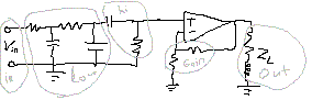
OK .. but this is just a concept drawing.. U1 and U2 are the LM3875TF's.. the other 2 opamp are just for simulation purposses...
Would this work?
Regards,
Thijs
Attachments
seems like a lot of extra componetns. like the 220ohm - 1ohm feedback path is included twice. it looks similar to what i suggested, except in my example, the 6.8k resistrors go to ground (highpass).
here is the non-inverting quick circuit. not sure what Qs are available, how robust the design is, ect... note that Rin should be assumed the be the first resistor, as this will be the worst case scenario.
here is the non-inverting quick circuit. not sure what Qs are available, how robust the design is, ect... note that Rin should be assumed the be the first resistor, as this will be the worst case scenario.
Attachments
Konnichiwa,
It is quite trivial. You can calculate the required values using an on-line tool from Analog Devices:
http://www.analog.com/Analog_Root/static/techsupport/designtools/interactiveTools/filter/filter.html
It does 2nd order inverting operation filters quite easily.
You need to select MFB LP/MFB HP from the filter type and enter a gain of 20 (26db) to get the schematic for a "filtered IGC".
For a bandpass you series simply a highpass and a lowpass circuit (around one Op-Amp).
It will be definitly worthwhile to buffer the input of such a Multiway Amplifer, here the Rasmussen Valve Buffer comes into it's own.
BTW, as nowadays Non-inverting Chipamps are the latest fashion, you can look at this TDA2030A Application note.
http://www.st.com/stonline/books/pdf/docs/1459.pdf
It shows (among other circuits) the circuit I started out with for my mid 1980's active speaker project (i used a pair of bass Amp's as I used dual woofers) but with different x-over points (250Hz & 5KHz).
Such a circuit can be realised with the LM3875 very easily, using for example a bridge Amp for the Woofer and Single Amp's for Midrange & Treble.
Also, equalisation for the drivers could be included into the feedback loop (eg LF lift to equalise a small box size sealed woofer or a rolloff in the upper midrange to counter the rising response of most Midrange/Woofer-Midrange drivers.
Sayonara
Cradle22 said:
Is it possible to convert the IGC design so that only high or low signals are amplified without adding additional op-amps?
It is quite trivial. You can calculate the required values using an on-line tool from Analog Devices:
http://www.analog.com/Analog_Root/static/techsupport/designtools/interactiveTools/filter/filter.html
It does 2nd order inverting operation filters quite easily.
You need to select MFB LP/MFB HP from the filter type and enter a gain of 20 (26db) to get the schematic for a "filtered IGC".
For a bandpass you series simply a highpass and a lowpass circuit (around one Op-Amp).
It will be definitly worthwhile to buffer the input of such a Multiway Amplifer, here the Rasmussen Valve Buffer comes into it's own.
BTW, as nowadays Non-inverting Chipamps are the latest fashion, you can look at this TDA2030A Application note.
http://www.st.com/stonline/books/pdf/docs/1459.pdf
It shows (among other circuits) the circuit I started out with for my mid 1980's active speaker project (i used a pair of bass Amp's as I used dual woofers) but with different x-over points (250Hz & 5KHz).
Such a circuit can be realised with the LM3875 very easily, using for example a bridge Amp for the Woofer and Single Amp's for Midrange & Treble.
Also, equalisation for the drivers could be included into the feedback loop (eg LF lift to equalise a small box size sealed woofer or a rolloff in the upper midrange to counter the rising response of most Midrange/Woofer-Midrange drivers.
Sayonara
Re: Re: How to add a high / lowpass to an IGC / GC?
I don't know that it's "trivial" -- in the sense of using the LM3875 itself as the opamp for the filter -- this is because the reactive components of the feedline and terminating load have to be taken into account, and the Overture series of power op-amps are easy enough to get oscillating...
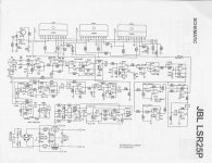
here's the JBL circuit I referenced before:
Kuei Yang Wang said:Konnichiwa,
It is quite trivial. You can calculate the required values using an on-line tool from Analog Devices:
I don't know that it's "trivial" -- in the sense of using the LM3875 itself as the opamp for the filter -- this is because the reactive components of the feedline and terminating load have to be taken into account, and the Overture series of power op-amps are easy enough to get oscillating...
here's the JBL circuit I referenced before:
Attachments
HP-LP direct
Hi Folks, I have been thinking and simulating on this subjet as well. Came to the conclusion it is better to use a separate OP for the filters.
Reason 1 is that for the low pass filter the high frequency gain seen by the OP is 1 and the 3875/3866 are not stable below a gain of 10.
The next reason is that when the gain is high the filter coefficients for a Sallen-Key filter are very sensitive. So component tolerances will lead to unacceptable deviations from the required curves.
Good luck Rick
Re: HP-LP direct
i sucessfully built a variable low pass Sallen-Key filter once using fixed caps and a variable resistor (double gang), it sounds fine..
you could try that, im sure having some variation in the resonant frequency would be beneficial anyway so you could 'tune' the sub
Rick NL said:
The next reason is that when the gain is high the filter coefficients for a Sallen-Key filter are very sensitive. So component tolerances will lead to unacceptable deviations from the required curves.
Good luck Rick
i sucessfully built a variable low pass Sallen-Key filter once using fixed caps and a variable resistor (double gang), it sounds fine..
you could try that, im sure having some variation in the resonant frequency would be beneficial anyway so you could 'tune' the sub
Re: HP-LP direct
Konnichiwa,
This applies only to the IGC and is fixed very trivially of course, if you know how (place a cap from the inverting output to ground sized so the noise-gain never drops below 10).
Using the non-inverted topology the minimum gain is always there.
BUT, if you build the Inverting circuit with filters you do not use Sallen Key and had you read the attached document.....
http://www.st.com/stonline/books/pdf/docs/1459.pdf
....you would know how to make a Sallen Key filter using the values for gain = 1 but with a gain of 20.
Hardly. You nowadays have 1% Capacitors and resistors with < 0.1% tolerance and if (for arguments sake) you make each and every critical value up from several paralleled 1% tolerance capacitors geometric averaging brings the tolerance down further.
So, I repeat, inverting or non-inverting, incorporating active filters up to 2nd order WITHOUT added external Op-Amp's IS trivial. TheSallen key variant worked just fine around 20 Years ago, so why not now?
If using MFB I personally would use a 3rd Order HP and a subtractive Lowpass filter anyway, with some LF EQ in the Feedback loop of the woofer amp to counteract the usual rising response from the common HiFi Woofers.
Maybe I really need to draw out a circuit for such trivial stuff?
Sayonara
Konnichiwa,
Rick NL said:Reason 1 is that for the low pass filter the high frequency gain seen by the OP is 1 and the 3875/3866 are not stable below a gain of 10.
This applies only to the IGC and is fixed very trivially of course, if you know how (place a cap from the inverting output to ground sized so the noise-gain never drops below 10).
Using the non-inverted topology the minimum gain is always there.
Rick NL said:The next reason is that when the gain is high the filter coefficients for a Sallen-Key filter are very sensitive.
BUT, if you build the Inverting circuit with filters you do not use Sallen Key and had you read the attached document.....
http://www.st.com/stonline/books/pdf/docs/1459.pdf
....you would know how to make a Sallen Key filter using the values for gain = 1 but with a gain of 20.
Rick NL said:So component tolerances will lead to unacceptable deviations from the required curves.
Hardly. You nowadays have 1% Capacitors and resistors with < 0.1% tolerance and if (for arguments sake) you make each and every critical value up from several paralleled 1% tolerance capacitors geometric averaging brings the tolerance down further.
So, I repeat, inverting or non-inverting, incorporating active filters up to 2nd order WITHOUT added external Op-Amp's IS trivial. TheSallen key variant worked just fine around 20 Years ago, so why not now?
If using MFB I personally would use a 3rd Order HP and a subtractive Lowpass filter anyway, with some LF EQ in the Feedback loop of the woofer amp to counteract the usual rising response from the common HiFi Woofers.
Maybe I really need to draw out a circuit for such trivial stuff?
Sayonara
Re: Re: HP-LP direct
Hi!
That's just what I was looking for. No need to use an IGC... It's just what I fiddled around with before...
But, in the PDF from Thomson, there are no formulars of how to calculate the values of C1, C2, C3 and R1, R2, R3 from figure 19 ("Active Power Filter").
I understand that I could chose C1=C2=C3 freely, and adjust R1-R3 to the cap value. But by which formula?
Thanks again...
Arndt
Hi!
Kuei Yang Wang said:
http://www.st.com/stonline/books/pdf/docs/1459.pdf
....you would know how to make a Sallen Key filter using the values for gain = 1 but with a gain of 20.
That's just what I was looking for. No need to use an IGC... It's just what I fiddled around with before...
But, in the PDF from Thomson, there are no formulars of how to calculate the values of C1, C2, C3 and R1, R2, R3 from figure 19 ("Active Power Filter").
I understand that I could chose C1=C2=C3 freely, and adjust R1-R3 to the cap value. But by which formula?
Thanks again...
Arndt
Re: Re: HP-LP direct
Would you mind if I ask you to do so ? I'm about to build mine, and like to check...
Kuei Yang Wang said:Konnichiwa,
Maybe I really need to draw out a circuit for such trivial stuff?
Sayonara
Would you mind if I ask you to do so
? I'm about to build mine, and like to check...Re: Re: Re: HP-LP direct
Konnichiwa,
They are exactly the same as standard Sallen Key Filters aranged around a Follower. They figured the formulas are well known enough.
If you don't fancydoing it the oldfashioned way with tables and slip stick you can use the "Net-Age" filter calculator (the link to which was posted earlier in this thread) here:
http://www.analog.com/Analog_Root/static/techsupport/designtools/interactiveTools/filter/filter.html
Simply select "Sallen Key LP" or "Sallen Key HP", the desired filter type (Bessel, Butterworth etc.) Frequency and Filter Order (I would not go above 3rd order - if so you can place the 3rd section ahead of the 1st filter stage, taking care of keeping the impedance at 1/10th or lower (meaning C = 1 X C for the first stage).
It is at any extent exactly teh same filter math as everywhere else....
Sayonara
Konnichiwa,
Cradle22 said:
But, in the PDF from Thomson, there are no formulars of how to calculate the values of C1, C2, C3 and R1, R2, R3 from figure 19 ("Active Power Filter").
They are exactly the same as standard Sallen Key Filters aranged around a Follower. They figured the formulas are well known enough.
If you don't fancydoing it the oldfashioned way with tables and slip stick you can use the "Net-Age" filter calculator (the link to which was posted earlier in this thread) here:
http://www.analog.com/Analog_Root/static/techsupport/designtools/interactiveTools/filter/filter.html
Simply select "Sallen Key LP" or "Sallen Key HP", the desired filter type (Bessel, Butterworth etc.) Frequency and Filter Order (I would not go above 3rd order - if so you can place the 3rd section ahead of the 1st filter stage, taking care of keeping the impedance at 1/10th or lower (meaning C = 1 X C for the first stage).
It is at any extent exactly teh same filter math as everywhere else....
Sayonara
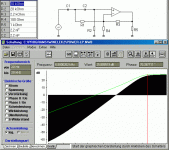
Hi again,
The implementation on the STonline shows that it can be made to work.
One thing is important with this topology: the feedback resistors shall be low ohmic in comparison to the filter resistors.
I have added two simulations in Winelektronik, one with a 2k2/100 Ohm feedback branch and the green line with 220k/10k resistors.
The highohmic version leads to only a 6 dB/octave slope for a 2nd order topology, while the low ohmic version remains 12 dB untill the response is about 70 dB down.
The topology I referred to in my first reply has R1 from the capacitor node to the output of the Amp. This topology does not suffer from the level off to 6 dB/octave but it is rather sensitive to component changes.
Rick
Attachments
- Status
- This old topic is closed. If you want to reopen this topic, contact a moderator using the "Report Post" button.
- Home
- Amplifiers
- Chip Amps
- How to add a high / lowpass to an IGC / GC?