Long story short, I've got an extra transformer with 120V 250mA secondary (+ 100V tap) and two 6.3V 2A heaters. 120V rectified isn't a lot to work with for B+, so I've been reading up on voltage doubling. But something gave me pause, namely:
from here.
Is this just a practical consideration relative to the capacitors needed in making a voltage doubler (ie higher currents would require silly capacitors)? Seems to me that the current required for B+ on something like a 6Y6 is pretty small in the grand scheme of things.
Anyone have a good link to more reading on voltage doublers or some advice? Still looking for good schematics to make use of this transformer, too!
The voltage doubler is an integral part of the alternating current rectification process and helps in increasing the voltage of the system. As the name suggests, it produces voltage which is almost twice than the input voltage. This means that the voltage generated by the doubler is twice the peak value of the alternative input current. However note that this is possible only if the load current is very small.
from here.
Is this just a practical consideration relative to the capacitors needed in making a voltage doubler (ie higher currents would require silly capacitors)? Seems to me that the current required for B+ on something like a 6Y6 is pretty small in the grand scheme of things.
Anyone have a good link to more reading on voltage doublers or some advice? Still looking for good schematics to make use of this transformer, too!
Ah,yes the one that came with the wind :lol
Think ,how much power is there ?120Vx250mA=30W but rectifiers are a bad load,mostly heavy pulses,so count 20W.
The doubler gives 2x(120x1,4)=336V.With 20W you have a current of 20/336=round 60mA.
The usable voltage will be somewhat less than 336V (losses;rectifier,trannie)but the losses also consume power.
Mona
Thanks for the input Ketje and Mooly!
I don't have a particular design in mind, so the potential load is a bit up in the air. I could possibly use a tube buffer (I don't really need a preamp). I wonder if something with a couple of 6SL7s would work? Those are a pretty minimal load, are they not?
Something like John Broskie's ACF buffer?
Last edited:
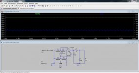
This wasn't a sim for this question but it illustrates the idea. Green trace is the output voltage. Blue is the transformer current with a 10 ohm internal resistance. It gives you a rough idea what to expect. The load is pulling around 90ma.
Edit C1 and R1 aren't relevant to the doubler.
Edit C1 and R1 aren't relevant to the doubler.
Attachments
Thanks, Mooly! Sounds like I'm limited to some fairly low plate current tubes if voltage doubling. For a buffer it may work out. I can't think of much to use this for if not doubling the voltage, either. The 6y6 has potential at the lower voltage, but then the problem becomes a driver that can also operate at such low voltage.
Using the same principle, You can also create a voltage tripler, or even times four.Thanks, Mooly! Sounds like I'm limited to some fairly low plate current tubes if voltage doubling. For a buffer it may work out. I can't think of much to use this for if not doubling the voltage, either. The 6y6 has potential at the lower voltage, but then the problem becomes a driver that can also operate at such low voltage.
DF96, do you have any links or suggestions on where I can read more about the relationship between cap size and DC voltage output? I have a basic understanding of doublers, but no experience building/calculating them. Thanks!
I had considered multiplying the voltage even more, but I'm worried about how much current I'd have left to play with.
I had considered multiplying the voltage even more, but I'm worried about how much current I'd have left to play with.
The losses go up as the square of the voltage multiplication.
The resistive losses in a doubler are roughly 4times as bad as in a non doubled rectifier solution.
If you work with 2200uF per Ampere of peak output current for a conventional (non doubled) then by adopting similar component specification and restricting the peak output current to 250mApk gets you a guide on what you may want to experiment with.
Some will use a very different XXuF per ampere component sizing.
I built a little doubler and a quadrupler so that I could measure the voltage drop on load to see if this squaring rule held up. It does.
The voltage droop of the quadrupler was enormous as load current was increased. I was looking for +-60Vdc @ 20mA from a 15Vac winding. The doubler and quadrupler should have increased the nominal +20Vdc to +40Vdc and +80Vdc. It did. But the 80Vdc drooped very quickly below my 60Vdc target before the load current reached 20mA.
Sorry, no. I just use the definition of capacitance (C=Q/V) and work it out.Sodacose said:DF96, do you have any links or suggestions on where I can read more about the relationship between cap size and DC voltage output?
Look for stuff on cap input DC power supplies, or AM envelope detectors - they are the same thing used for different purposes.
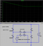
energy conservation gets you to the transformer like impedance equations
with winding Lm, Rseries, turns ratio estimates you can approximately model the mains xfmr in spice, load with various V multipliers, change C, add ESR to C, change load current in sim
below you can also see a startup overshoot:
with winding Lm, Rseries, turns ratio estimates you can approximately model the mains xfmr in spice, load with various V multipliers, change C, add ESR to C, change load current in sim
below you can also see a startup overshoot:
Attachments
Thanks all for the info. It seems shooting for a low load is going to be a necessity if I'm going with a voltage doubler. That's going to rule out using this for any kind of single-ended amplifier (I was considering a 6Y6 design). That's fine with me, as I don't need one.
I'm reading through some tubecad articles on the ACF series of buffers and some tube datasheets. I think I'm going to try my hand at a 6SL7 or 6CN7 Aikido style buffer. Just a couple of small tubes should be safe with a voltage doubler (and I'm going to be right at the 250V sweet spot for these tubes). Here's the relevant article.
Somehow I didn't see the voltage doubling option in PSUD2! I'll have to dig a little deeper. I've found that little piece of software to be a huge help in the past.
Hope this helps:
An externally hosted image should be here but it was not working when we last tested it.
- Status
- This old topic is closed. If you want to reopen this topic, contact a moderator using the "Report Post" button.
- Home
- Amplifiers
- Power Supplies
- How much load is too much load on a voltage doubler?