Only a few watts are needed to run the Bias supply as only a few microamps is required to charge the diaphragm.
The Bias voltages range from about 2Kv to 5Kv.
But, I have ran voltages as high as 10Kv to 14Kv on my DIY panels and 25KV peak to peak across the stators, this is very hard to accomplish at these levels of voltages.
Voltages half of that on a large panel of about 1'X4' can be/would be very loud and more than enough for most.
The Toroid things are common 240V/6V power transformers only hooked up in reverse as a step up transformer.
Typically you need at least a 1:80 or more transformation ratio so you would need to use two of them per panel, if using the common types being used on a few systems in these threads.
Using these particular types of transformers can only be used in a Hybrid type of system were a woofer handles everything below about 300Hz to 500Hz or so.
You need an amp that can handle a very low impedance as ESL's impedance can typically fall to below 1 or 2 ohms at times depending on the setup.
Their lowest impedance is always at the highest frequency it is producing as they are a purely capacitive device.
jer")
The Bias voltages range from about 2Kv to 5Kv.
But, I have ran voltages as high as 10Kv to 14Kv on my DIY panels and 25KV peak to peak across the stators, this is very hard to accomplish at these levels of voltages.
Voltages half of that on a large panel of about 1'X4' can be/would be very loud and more than enough for most.
The Toroid things are common 240V/6V power transformers only hooked up in reverse as a step up transformer.
Typically you need at least a 1:80 or more transformation ratio so you would need to use two of them per panel, if using the common types being used on a few systems in these threads.
Using these particular types of transformers can only be used in a Hybrid type of system were a woofer handles everything below about 300Hz to 500Hz or so.
You need an amp that can handle a very low impedance as ESL's impedance can typically fall to below 1 or 2 ohms at times depending on the setup.
Their lowest impedance is always at the highest frequency it is producing as they are a purely capacitive device.
jer
Last edited:
thanks
So how do the toroids get from 6 volts to kilovolts? Dont they go from 6 to 240 volts? And does the 6 volts come from the amp? Also what is the voltage on the diaphram? and is it possible to charge the diaphram from batteries? Is the part that plugs into the wall the part that charges the diaphram?
Thanks
The important thing with a transformer is the turns ratio. 240 volts in and 6 volts out is 40 to 1. So in reverse 1 volt in and 40 volts out. Transformers work either way round, to step up or down. So 60 volts in and you get 2400 volts out. Feed the output of one transformer into the input of another and you can step up (or down) again. A major limiting factor is the insulation of the windings, each to the other and also to the core.
You can run a transformer from a battery by using an electronic circuit to deliver an AC waveform to the transformer.
You can run a transformer from a battery by using an electronic circuit to deliver an AC waveform to the transformer.
![ESL_animation[1].gif](/community/data/attachments/310/310208-f5c4f05a4234f1e0c5e97335bc25a1d7.jpg)
Hi,
The mains is used to charge the stators and current draw is
tiny once they are charged, being simply the leakage current.
DC cannot be easily stepped up. A small transformer (plus
rectifiers) steps up the AC mains for the DC for the stators.
A much bigger one steps up the AC signal for the diaphragm.
rgds, sreten.
Last edited:
I usually see about 3 - 3.5 Kv on most Acoustat diaphragms some times a little more but not often. I like to add two more multiplier stages to bump the voltage as high as possible. This will depend upon the condition of the speakers.
The mains are used to charge the diaphragm not the stators (in most set ups). Your amplifier drives the stators via the two step up transformers (in an Acoustat). There are some ESL speakers which are set up the way Sreten describes but not many. Hope this helps. voltages will vary with different designs. Best regards Moray James.
The mains are used to charge the diaphragm not the stators (in most set ups). Your amplifier drives the stators via the two step up transformers (in an Acoustat). There are some ESL speakers which are set up the way Sreten describes but not many. Hope this helps. voltages will vary with different designs. Best regards Moray James.
You must also remember that when using power toroids in reverse for ESL that you must limit the lowest frequency operation per volts input as well to avoid saturation of the core causing distortions of the signal and extreme overloads to the amplifier.
This is a very simple rule as most ESL setups are of a hybrid design and goes as follows,
Being that the transformers are designed for 60HZ (or some that are for 50Hz as well) you can't put more voltage in to any winding than what it is rated for at 60hz.
otherwise you will saturate the core.
This goes for primary and secondary winding's alike.
No more than 240v into the 240v winding ( or two 120v's in series) and no more than 6Vrms into the 6v winding at 60Hz or 50hz for some.
But you ask " Then how do I put 60Vrms into the 6v winding and get 2400Vrms out of the 240v winding?".
Here is why,
If you double the frequency going into the winding of the transformer then you can double the voltage across the winding as well without saturating the transformer's core.
Therefore in order to be able to input 12Vrms into the 6V winding you must make sure that the frequency of the signal that goes into the winding must not be less than 120Hz.
Then you can safely input 12v into the 6v winding without cuasing any core saturation issues and this will double your output voltage on the 240V winding to 480vrms as well.
Then 24v at no less than 240HZ as well and so on.
This is a linear function of reciprocals so for 30Vin/6V for the winding =5, 5 * (the winding frequency of) 60hz = 300hz.
So for your average amplifier of 100watts (28Vrms) you must never let any frequency's lower than 300Hz enter into the transformers 6V winding at a 30V level.
The same goes for the above example of 60Vrms into the 6V windng and that frequency of course would 600Hz.
That is how we get away with using these types of transformers as a woofer covers the lower frequency's below that point of cutoff.
Read through this thread,
http://www.diyaudio.com/forums/planars-exotics/161485-step-up-transformer-design.html#post2088330
It will help you to have a better idea of how this technique works as I go through the analysis of one of my cores that I had purchased a bunch of for cheap.
It also goes well into the theory and the hows and why's as well as many other factors besides the transformation ratio in how to make them work properly.
I found out as well that they work pretty good if one chooses not to want to wind from scratch.
I also show how to add your own custom primary winding to change to a custom transformation ratio following the same rules I just described.
It may be possible to get by with a single core instead of two per panel using this technique.
I have done this but there are limitations and the reasons are explained in the thread and I will explore this more in my next article.
I am working on a newer up too date article using the Antec AS-1206 power transformer for ESL's.
It won't be as confusing and will be more straight forward then that last thread because I was still learning myself at the time.
Also I had run into a few issues in testing that I had since worked out.
I will try to explain what those issues are again in the new article as I have described them on occasion in other threads.
Cheers !!
Jer
Last edited:
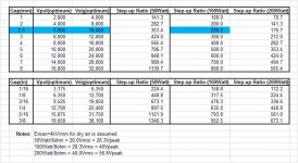
Here is a neat little chart that I found somewhere that can give you an idea of the voltages involed in powering an ESL as per D/S and amp power size.
It doesn't take into account for panel size or added transformer capacitance as it is just a generalization of typical parameters.
Enjoy!!
jer
It doesn't take into account for panel size or added transformer capacitance as it is just a generalization of typical parameters.
Enjoy!!
jer
Attachments
Here is a neat little chart that I found somewhere that can give you an idea of the voltages involed in powering an ESL as per D/S and amp power size.
The chart was posted here:
http://www.diyaudio.com/forums/plan...rrent-vs-voltage-drive-esl-6.html#post2358418
It was created based on Section 3.2.9 of Baxandall's chapter on ESLs where he derives values for Vbias and Vstator to maximize ESL output.
What limits the efficiency of ESLs is the the breakdown voltage for air. Emax is a function of D/S spacing and stator smoothness.
He used a value of Emax=4kV/mm for calculations on the QUAD ESLs.
For a given diaphragm spacing d, the optimum Vbias and V(stator-stator) are:
Vbias = Emax x d / 2
V(stator-stator) = Vbias x 2
For example, an ESL with 2mm spacing between diaphragm and stator you will maximize peak SPL with:
Vbias = 4000 V
V(stator-stator) = 8000 V
If you plan to use a 100Watt amplifier(28.3Vrms = 80Vpp) you will need a transformer with a step-up ratio of 100:1 to achieve the maximum possible SPL.Using a larger step up ratio will not increase the peak SPL, it will only allow you to achieve the peak SPL with a lower voltage from your amplifier. Trying to increase the stator voltage beyond 8000V with 4000V bias will result in the air conducting(arcing-hissing) and not an increased SPL. If your maximum stator voltages are <8000V then you can increase output and sensitivity by dialing up your bias voltage.
The way to make ESLs louder is to increase the area. Equations for required Area given a desired SPL is covered in Section 3.3.9
Here is the reference.
P. J. Baxandall, “Electrostatic Loudspeakers,” in
Loudspeaker and Headphone Handbook, J. Borwick, Ed.
(Reed Educational and Professional Pub., Woburn, MA,
1998), pp. 106–195.
Thanks Boserst!!!
I had found it while I was sorting through some files and I had no label on it.
I figured it was based along the lines you describe.
I have ran bias voltages as high as +10kv and transformation ratios as high as 1: 200 to 400.
This greatly increased the sensitivity to where a 10v to 20v p-p input was more than enough to make may little panel to get very loud at +106db at 1meter ( and about nearly 110db at .5meter).
I can't even imagine what a larger panel is going to be like,But I will soon.
I have found that getting voltages above 8kv proves to be very difficult to contain although not impossible.
I have a new build that should sustain these voltages better than the last one.
My last panels with a diaphragm size of 3.25" X 9.75", I had pushed them to ionization of the air in the gap and they were so loud that I couldn't notice any distortions caused by the ionizing.
What was nice was that it took less than 4V p-p to have a comfortably loud SPL for normal listening using my smaller 80watt cheapy amp.
Suitable for maybe a small class A amp of some sort and still provide plenty of SPL's for enjoyment.
Getting a woofer ( not to mention a small one) to keep up is the new challenge!!!
Cheers !!
jer
Last edited:
Hello.I was order and plug to panels 2x 2x110v 2x6v 50VA toroids and with fullrange signal and highest levels have alot of distorsion.If i understand if i want to plug amplifier with 30v pp transformer will be around 2x30v 2x300v for full range?So if i want drive full range panels what to tell transformer manufacturer?Regards
Last edited:
Hi,
it has been stated quite repeatedly -lastly in #3 of this thread(!)- that the standard power toroids are not useably for fullrange-ESL useage.
They are designed for efficient useage of their core material and wire at the power line frequency, hence 50Hz or 60Hz. To allow for higher input voltage the signal frequency must be raised.
Also, the summed resistances of amp and transformer combined with the inductance of the transformer defines the lower bandwidth limit.
A lower bandwidth limit requires a higher inductance.
This in turn requires more windings, which in turn requires a larger core.
Larger panels with higher capacitance require larger cores.
I suggest at least 50VA for a 1nF panel @>300Hz. 80VA seems optimal.
A 2nF panel may be driven by 120VA core toroids from >150Hz on.
I´d like to point out that I don´t recommend the useage of toroids with dual primaries and dual secondaries, but single prim/single sec instead.
It was an experiment by Charlie which went ok with the trannies he chose, simply because he couldn´t source 230V/6V toroids easily.
While the flashover treshold of single windings trannies is clearly defined/specified and sufficently high (4kVrms and more), the multiple windings toroids flashover treshold between the two secondaries(!) may be as low as 500Vrms.
Another point to keep in mind regards the transformation factor.
Mostly the transformer is viewed as a voltage/voltage and current/current converter. But its also - and I dare to say even more so, due to the quadratic relationship- a impedance converter.
Its of low reward to only calculate voltage or current relationships if the impedance values don´t blend. Standard amplifiers are optimized to drive load impedances between 4 and 8 Ohms and depending on their stability within a phase angle range of ~+-45° (with a certain tolerance for lower and higher values). The transformer is now asked to transform the very high valued and very high phase-angled impedance of the panel to a lower and amp-acceptable range of values.
Beeing closer to ideal than other transformers, toroids present the amlifier more of the ´reactive´nature of the panel, i.e. the phase angle the amplifier has to cope with may reach very high values, close to the theoretical 90°.
It´s this phase angle that many amplifiers can´t cope with, not the low impedance at the upper bandwidth limit (where the phase tends to 0° again), as it may drive the amp into a ringing step response and even oscillation.
So take a moment and think about Your amps capablities with regard to stability into reactive loads.
Fortunately it seems, that if certain basic design parameters -namely efficiency of the panel- are chosen correctly, most other important design values fall into the right place like in a mechanical watch, at least for non-segmented metal-sheet panels. Segmented wire stators typically require higher transformation factors (>1:100) which would ask for 2x2 secondary lowvoltage windings with standard power trannies.
Afaik nobody has reported about such a setup yet.
I only tested wire stators positive with arrays of simple EI 230/6V trannies, but that could be a hint that the toroids will work in this application also.
jauu
Calvin
So if i want drive full range panels what to tell transformer manufacturer?Regards
Are you asking what specifications to give a transformer manufacturer for them to build you a custom transformer for full range operation of your ESLs? If so the starting point, as Calvin mentions, is to define what power amplifier you will be using, and what the impedance of the ESL panel is. How big is it? What is its capacitance, is it segmented?
- Status
- This old topic is closed. If you want to reopen this topic, contact a moderator using the "Report Post" button.
- Home
- Loudspeakers
- Planars & Exotics
- how much electricity do you need to run an esl speaker?