ray_moth said:Thanks for that Electrovoice article, very interesting! I'll have to study it. BTW, I know it's not your main point here but I notice that they use a 12AX7 for the concertina splitter. I didn't think it was supposed to be a particularly good choice?
I am sure there were bean counters in the old days too. So, 12AX7 may not be the best choice. I have never used that tube before, so I can't vouch for it.
I am referring to the Cf output stage and usage of 2 floating power supplies.
ray_moth said:I wonder how important tube quality is for cathode follower duty?
Getting back to Ray's original question, I think a case can be made that BOTH high-mu and high-gm are desirable in a tube for CF duty.
I see the evidence in the CF gain equation (of which there are several versions that are all valid and derivable from one another). In one version of the CF voltage gain equation, there is the term “mu/(mu+1)”, which captures the dependence of the CF’s built-in feedback on mu. All else being equal, for lowest distortion, you’d want that term to be very close to “one”, which means that mu must be high enough for it to be nearly equal to mu+1. When mu is high, there is therefore less dependence in the gain equation on mu. Although mu is usually the least variable of the three major tube parameters (mu, gm, rp) it is always somewhat variable (“non-linear”), so that we’d like to minimize dependence upon it. It is entirely possible to conceive of a CF with a high, but variable, mu tube that makes less distortion than a low, but more constant-mu tube.
As a more reasonable example case, consider two equally “linear” tubes, one with a mu of 100, the other with a mu of 20:
If mu were 100, then mu/(mu+1) is 100/101 = 0.990. If mu varies by +/-10% across the signal swing, then mu/(mu+1) will vary between 0.989 and 0.991, a change of about +/- 0.1% from the center point, which would create very little distortion.
If mu were 20, then mu/(mu+1) is 20/21 = 0.952. If mu varies by +/-10% across the signal swing, then mu/(mu+1) will vary between 0.947 and 0.957, a change of about +/- 0.5% from the center point, which would create far more distortion, maybe even 5 times the distortion (all other factors being ignored for now).
And I agree with Eli and the others about a CF needing high gm too. The output resistance (“rout”) of a CF (ignoring the parallel influence of Rk) equals rp/(mu+1). If mu is fairly high, this approximates to rp/mu, which is then 1/gm. If gm is high, then rout, the output resistance, is low. While this may be good for bandwidth, it is also good for distortion. Think of the other factor in the CF voltage gain equation: RL/(RL+rout). This is simply the voltage divider equation made up of the series rout and the shunt RL. RL should be much greater than rout so that this term tends toward “one”. When it does, the gain is no longer dependent upon rout, which is a non-linear term. When RL is infinite, gain is completely free of dependence on gm, but then why would we need a CF to drive an infinite load? We use CFs to drive burdensome loads. So, to make RL>>rout, we can either try to increase RL (adding a CCS in the cathode helps) or we can decrease rout (or both). Since RL is usually given to us as a fixed challenge, the only option is to reduce rout. Since rout = rp/(mu+1), which is approximately 1/gm, rout is determined by “non-linear” (actually “non-constant”) parameters, notably gm. Choosing high gm reduces gain dependence on gm. So, once again, it is entirely possible to conceive of a CF with a high, but variable, gm tube that makes less distortion than a low, but more constant-gm tube. However, in practice, gm is quite variable in all triodes, and picking tubes for more constant gm is rarely discussed; whereas mu CAN be selected for constancy.
Given the above, consider the case of the 12AU7. It has moderately low mu and low gm, at least compared to common alternative tubes for CF service. And mu is quite variable in a 12AU7 to boot. It doesn’t meet the high-mu, high-gm criteria. So can a 12AU7 work as a CF? Sure! The feedback in a CF can keep distortion to “acceptable” levels even with lesser tubes. In an absolute sense and in particular roles, performance may be “good enough” with a 12AU7 or a similar less-than-ideal tube. Some might even prefer the sound of the even-order distortion products that are created. But in a relative sense, we can probably do better with another tube in almost every circumstance where we’d consider a 12AU7 CF. When we’re asking what would be generally best for a CF, as we are here, we should come back to high-mu and high-gm as good first-look selection criteria. Other factors matter too: constancy of mu, large signal limits, onset of grid current, cathode current capability, heater-to-cathode voltage ratings, distortion cancellation with other stages, etc.
The mu argument is a good one, but looked at from the other direction, you can make exactly the same argument about gm- if it's very high, its reciprocal is small, and the resulting distortion from variation is reduced since the voltage divider ratio between the 1/gm and load resistance is likewise close to unity.
Ideally, you'd have high mu and gm simultaneously. That's possible, but carries cost.
Ideally, you'd have high mu and gm simultaneously. That's possible, but carries cost.
SY said:The mu argument is a good one, but looked at from the other direction, you can make exactly the same argument about gm- if it's very high, its reciprocal is small, and the resulting distortion from variation is reduced since the voltage divider ratio between the 1/gm and load resistance is likewise close to unity.
That's exactly what I was trying to say in my second to the last paragraph above.
Ideally, you'd have high mu and gm simultaneously. That's possible, but carries cost.
In a relative sense, a 6DJ8 or a 12AT7 (either carries little cost) would be better than a 12AU7 for most CF duties, just to pick a comparison among three common tubes using my dual criteria. I don't say that only a D3A or a triode-connected 7788 would qualify for a CF - those are penultimate choices, but carry a cost, as you say. I just propose the dual critera as a first look for comparing any two tube options on a relative basis.
Besides high mu and high gm, I mentioned that there are other factors that can tip the scales. As an example of my own departure from the dual criteria, I am reminded of the many times I’ve used a 6SN7 (which has only moderate mu and moderate gm) as a CF. When I’ve needed extreme voltage swings, I think of the good old 6SN7. Distortion is usually very good, despite not meeting the desired criteria, since mu is quite constant and its presence in the gain equation is relatively benign.
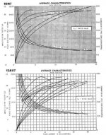
The attached characteristics give some clues to performance for the 6SN7 and similar-parameter 12AU7. I don’t mean to single out the 12AU7 for beating; it’s just that it’s so common and it comes to mind so readily.
The attached characteristics give some clues to performance for the 6SN7 and similar-parameter 12AU7. I don’t mean to single out the 12AU7 for beating; it’s just that it’s so common and it comes to mind so readily.
Attachments
Excellent analysis.
One is tempted to see the 12AU7 as a miniature 6SN7 - sort of - but the difference is enough to count.
Brian hinted at something sometimes overlooked, and that is the maximum amplitude. Also, folks are tempted to calculate the Zout, and then say fine, I can now drive this or that. One must keep in mind that Zout achieved by feedback (as it is in the CF) does not necessarily guarantee driving power into the following load. The maxima of such a circuit must also be investigated.
Again perhaps only confirming what has been said above, but folks do seem to fall into that trap. I have seen CFs in designs that would be unsuitable for the task.
Edit: Typo
Simultaneous high gm and mu: the reductio here, dangerously, is a Darlington emitter follower.
Johan's point cannot be stressed too highly- low loading of a cathode follower is a poor idea. Low source Z does NOT equal high current capability, and vice versa. Figure out your maximum signal current, taking into account desired bandwidth and load reactance, then choose a tube that can idle at a minimum of ten times that.
Johan's point cannot be stressed too highly- low loading of a cathode follower is a poor idea. Low source Z does NOT equal high current capability, and vice versa. Figure out your maximum signal current, taking into account desired bandwidth and load reactance, then choose a tube that can idle at a minimum of ten times that.
SY said:Johan's point cannot be stressed too highly- low loading of a cathode follower is a poor idea.
Cathode followers work best as a Lo-Z output into a Hi-Z circuit, such as driving a tone stack where you don't want the Zi to affect the frequency response. Look at cathode follower OTL designs and see just how inefficient they really are.
Low source Z does NOT equal high current capability, and vice versa. Figure out your maximum signal current, taking into account desired bandwidth and load reactance, then choose a tube that can idle at a minimum of ten times that.
Actually, I think that's a bit much. What I do is apply the "Rule of Five" that I use for SS design (i.e. The collector current should be at least 5X the base current of the next stage.). It works just fine for figuring idling current of CF grid drivers for good slew rate performance. You can always figure the current capability of the CF from: I= Vpp/(rp + Rk || Rl). CF drive also works for easy, Class AB2 loads, like a 6L6. If you need something with a bit more "moxie", use a MOSFET source follower.

Yes, indeed, SS devices may actually offer a better solution than a tube. High gm is certainly no problem. A MOSFET sf may be the best solution of all, what do you think? (I wasn't going to bring this up, for fear of being accused of hijacking my own thread, but since somebody else has, let's go for it!)
ray_moth said:Yes, indeed, SS devices may actually offer a better solution than a tube. High gm is certainly no problem. A MOSFET sf may be the best solution of all, what do you think? (I wasn't going to bring this up, for fear of being accused of hijacking my own thread, but since somebody else has, let's go for it!)
Just like to point out that Gary Pimm's CCS uses a mosfet follower and many have said that his CCS sounds good.
There is also that mosfet driver stage used by that shirtless dude named tubelab.
Maybe a good question for OP. Where are you planning on using the CF?
ray_moth said:Yes, indeed, SS devices may actually offer a better solution than a tube. High gm is certainly no problem. A MOSFET sf may be the best solution of all, what do you think? (I wasn't going to bring this up, for fear of being accused of hijacking my own thread, but since somebody else has, let's go for it!)
There's no such thing as a "perfect" technology, and there never will be. Unless you're replicating 1930s circuits, there's no good reason not to employ sand where sand can do the job best. I'd rather use a SS CCS for an LTP tail load rather than force a balance by unequal plate resistors. For driving difficult loads, a MOSFET is simply better than trying to parallel a whole bunch of tubes to make a driver. Even with paralleling, you're not gonna come close to a MOSFET for current handling, and Lo-Z output. Just not gonna happen.
An externally hosted image should be here but it was not working when we last tested it.
About the only alternative would be xfmr coupling with low u, vertical deflection power triodes, and then you have the problem of wrapping your gNFB around that second xfmr.
I'll forego "purity" over effectiveness and put the sand in there where I need it.

ray_moth said:Yes, indeed, SS devices may actually offer a better solution than a tube. High gm is certainly no problem. A MOSFET sf may be the best solution of all, what do you think? (I wasn't going to bring this up, for fear of being accused of hijacking my own thread, but since somebody else has, let's go for it!)
Cause célèbre:
A prior post (long)
MOSFET transconductance at low currents may not be all that great
that shirtless dude named tubelab
That shirtless guy comments
And more shirtless guy
Brian Beck said:
In the case of the IRFP240, we need to worry primarily with Crss (= Cdg) which in the follower configuration is not amplified by the Miller effect happily. But it's bad enough. (We'll ignore the bootstrapped Cgs for simplicity). At the operating point of around 11 volts drain-to-source (Vds), Crss is about 350pF. To achieve a 200KHz roll-off (just for sake of example) we'd need to drive it with a resistance of no higher than about 2200 ohms, which is easily achievable with a decent triode's plate. Is all well then? No, read on...
Vds can vary by almost +/- 10 volts from this operating point as it swings with signal. The problem is that Crss varies from about 200pF at Vds = 20 volts to about 1300pF at Vds = 1.
Isn't that just a bit ridiculous? When doing designs incorporating MOSFETs, I'm looking at keeping Vds up there, not to swing from rail-to-rail. I also favor keeping the voltage up because capacitances begin to do wonkey things when the Vds drops too low. As for driving, I'm including a Kimmel to drive the source follower.
Then use a reasonable current, NBD.
I was trying to keep the thread general but, since you called me on itWhere are you planning on using the CF?
my specific interest had to do with the possibility of using some Sovtek 6SN7s that I have as cf drivers for EL34s in a PP amp (pentode or triode, haven't decided yet). I wondered if the Sovteks would sound OK as cfs, even if they're not so good in grounded cathode configuration. However, from reading the general trend of replies, it would seem that a higfher gm, higher mu tube (or a MOSFET) would be a better solution anyway. MOSFET's are OK by me, I'm not interested in 'purity' - this is a hobby, not a religion! Isn't that just a bit ridiculous? When doing designs incorporating MOSFETs, I'm looking at keeping Vds up there, not to swing from rail-to-rail. I also favor keeping the voltage up because capacitances begin to do wonkey things when the Vds drops too low. As for driving, I'm including a Kimmel to drive the source follower.
No. That was just one example. I've seen MOSFETs used with 20 to 50 volts of Vds but not swinging rail-to-rail. Even small signal voltages at those Vds levels are at risk. If you consider the ear's apparently extreme sensitivity to phase modulation as discussed briefly in my linked post, we’re not clearly out of the woods even at higher Vds. How high is good enough? That’s debatable and depends on driving impedance and other factors.
What's a "Kimmel"? As in Alan Kimmel? You must mean a mu-follower with low output Z - that certainly helps . Then why use a FET follower at all if you already have a mu-follower?
Then use a reasonable current, NBD.
You got me. I don't know what a "NBG" is either. I hope it's nice. If you're running your FET at very high Vds to reduce capacitance modulation effects, then how much drain current could you afford to crank through the FET to get the gm up without burning tens of watts of drain dissipation?
- Status
- This old topic is closed. If you want to reopen this topic, contact a moderator using the "Report Post" button.
- Home
- Amplifiers
- Tubes / Valves
- How important is the quality of a triode used as a cathode follower