millwood said:
isn't it always true that you will get worse sound once you get off the optimum bias point? That's by definition, right?
I think john curl and somebody else mentioned that the optimum bias point is to get about 25-30mv drop off the emitter resistor. an old HP patent or something like said it, as I recall. it was discussed a couple months back.
Yes and no.
Distortion at reasonable powers will always be higher for
non-optimium bias, but if the overbias is appreciable you get
a small class A low power region where it will sound better.
Overbias causes "gm doubling", once you've overbiased the
steps in gm don't get any worse so you might as run as hot
as is sensible to maximise the class A region.
EchoWars:
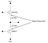
> Take your measurement from the emitters of the transistors! Find the 'D1047' device for one channel,
> and put your positive lead on its emitter. Find the 'B817' device for the same channel, and put the
> negative lead there. Now you cannot get it wrong!!!!!!
I wouldn't be so sure of that... What if the transistors were mounted the other way around, making the emitter leg on the outside left?! Well anway, I measured them according to your helpful diagram (thanks), assuming the emitter leg is outside right, I got about 7.7mV on one pair, 7.0mV on the other. So if I'm shooting for a "voltage drop" of 22mV, then a measurment of the emitter legs across two output transistors should read 22mV? Or is it the combined reading of two of the .22 ohm emitter resistors that should give this value? (I'm a little confused because it looks like you started suggesting I take a reading of the Sanyo output transistors, but that the reading should be 22mV across the .22 ohm emitter resistors, which are different parts).
As for not having a handle on the how to measure the emitter resistors, when I probed the left leg across two resistors, I got a reading of 7.0mV (probing the 2 legs of each resistor gives a reading of about 3.7mV). Probing the right and left leg across 2 resistors gives a reading not anywhere near the double of one resistor. Do I have a handle on measuring "across the resistors" now?
K-amps:
Thanks. I will take your advice and place a temp probe right near each output transistor, and instead of shooting for a certain value across the output transistors or emitter resistors, I'll shoot for an operating temperature comfortably below 50C (after waiting at least an hour to get a temp reading). I don't want to take it to the max. recommended operating temperature, because the amp might be left on overnight sometimes, if someone forgets to turn it off, and the temp could climb above the safe recommendation.
tube_dude, millwood etc.:
Thanks for the input & advice.
Measuring from emitter to emitter is the same as measuring across the two emitter resistors...(I'm a little confused because it looks like you started suggesting I take a reading of the Sanyo output transistors, but that the reading should be 22mV across the .22 ohm emitter resistors, which are different parts).
See drawing.
Attachments

 ...but this is pretty basic stuff.
Echo Wars:
He does have a point, and so do you. I'm a "newb", so I don't know how to read an electronics schematic. And its pretty 'basic stuff', but this stuff can easily become complicated and overwhelming to "newbs" if its explained in a less than simple way. Hence all the follow-up questions... So while I appreciate the effort, my resistors don't look at all like the line drawings in the diagram (and I haven't a clue as to where "Vcc" and "Vee" is). So when I go to do the measuring, I still wouldn't be sure which leg is the emitter and which is the collector, according to that diagram. But if for example, you say "Look newb, if they're attached to a heat sink, the emiiter leg is always on the outside right of the three legs", then there's no confusion. Or "the emitter legs will show -this- kind of a reading, the collector legs will show -this- kind of reading", then its real easy. I tend to learn by application rather than theory, so I believe I've already confirmed that the emitter leg is the outside right one of the 3 legs from the measurements I took of both outside legs across the two transistors. (Deduced from the fact that they were approximately the same value as the two emitter resistors combined; 7.7mV vs. 7.0mV).
Another good way to confuse a "newb" is to say that I should shoot for a "voltage drop" of 22mV; after its been established that my current voltage is about 7.7mV. That to me sounds like a voltage GAIN, unless you write -22mV. So I just logically assume from context and all, that it means I should PUMP UP the voltage to 22mV... and ignore the term "drop"! And I'm simplifying matters for myself by not worrying about things like "manufacturer's rated bias voltage" or how to measure it. If I know the output transistors should never go beyond 50C, then that's a simpler way for me to be sure I'm not overdriving the bias. So long as I know I'm not overbiasing, my ears will then take over the task of telling me whether a given bias is an improvement or not. Thanks for informing me enough to help me achieve this goal.
Hey fotzepolitic,
No disrespect was intended here and I am sure same sentiments by Echowars. Actually I commend his efforts to keep trying to help you despite gaining absolutely nothing material in return.
It is this spirit of sharing that helps us all to learn, we are all newbs in one way or ther other.
When Echowars said this is basic stuff, I guess he was referring to the fact that he did not have to draw up a complex diagram, just the basic output stage....
We know you are clueless thats why we are trying to help and will continue to do so.
Enjoy the thread,
Peace and respect!
K-amps
Any current flowing through a resistor causes a 'voltage drop' across that resistor, hence the phrase. So...when we say 'set the bias so you have a 22mV voltage drop across the resistors', we mean that you set the bias so that you will measure 22mV from the emitter of the 'D1047' to the emitter of the 'B817' device. Right now, you are measuring a 7mV 'voltage drop' across the resistors.Another good way to confuse a "newb" is to say that I should shoot for a "voltage drop" of 22mV; after its been established that my current voltage is about 7.7mV. That to me sounds like a voltage GAIN, unless you write -22mV. So I just logically assume from context and all, that it means I should PUMP UP the voltage to 22mV... and ignore the term "drop"!
RE: The transistors. I don't believe it is possible to mount them backwards...the collector is designed to be thermally coupled at the rear of the device, so reversing it would lead to quite poor thermal coupling to the heatsink, and the loss of a job for the moron who designed it that way. The emitter in on the right, just like the pic I posted.
I can't make it any clearer than I just have...if you are still confused, find a knowledgable friend to give you a hand.
Echo Wars:
> I can't make it any clearer than I just have...if you are still
> confused, find a knowledgable friend to give you a ha
No, I'm good, thanks. I wasn't confused any longer about measuring the voltage across the emitters (your pic combined with my experimenting with taking measurements to confirm the emitter leg was on the right side cleared that up). Only the term "drop" was a little bit confusing, but I could guess what it really meant. Thanks for your newb patience, and all the help. I just learned a new skill in the past couple of days (adjusting an amp's bias voltage), so that's always exciting.... It'll be interesting to see what effect playing with the bias will have on my amp's sound, or if I'll end up blowing it up real good....
Not if you're careful. I still suggest setting it to about 50mA (22mV across the emitters) and listening to it for a good several days. In my opinion, there is little or nothing to gain by cranking up the bias to levels above perhaps 75mA (33mV across the emitters).or if I'll end up blowing it up real good....
Have fun...don't kill it.

Helo,guys ! How can I control DC offset of STK 403 , I have an Yamaha-rx-v357 and all STK have 1 V DC offset on output, otherwise sound is clear if protection is deactivated...
I've found on Google : "I found that the +/- Pre voltages were very important in setting the DC offset on the output."
I've found on Google : "I found that the +/- Pre voltages were very important in setting the DC offset on the output."
The only thing bias current basically does is affect cross over distortion.
Even then this can only be heard at low listening levels.
If your playing loud it will be drowned out.
Too little bias and you get cross over distortion.
Too much bias and all you are doing is waste power as heat in the heatsink.
Some people say they like a higher bias I cant say I could noticed any difference when I tried it.
What about when you have 4 ouput transistors per channel and no bias points,
Manufacturer says bias it to 8.0mV over one of the 0.22R emitter resistors. But i get different value with each resistors.
I’m more used to a common biaspoint (like many commercial amps have)
For me very confusing this with mV and mA, often mix them up.
Anyway how can i bias so i get a common bias for all 4?
Transistors are a1943 and sc5200
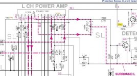
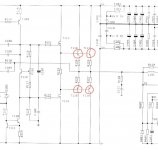
Example:
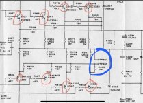
First is my amp (Copland CTA-420)
Second is a commercial normal amp with biaspoints (NAD218)
Both amps use same value on emitter resistors and same output trannies except twice as many in NAD.
Both manufacture recommend 8mV bias. But totally different measurements. Nad have tied 4x 10k resistors to the biaspoint?
Question is how are they thinking and how can i bias all trannies simultaneously?
Attachments
- Status
- This old topic is closed. If you want to reopen this topic, contact a moderator using the "Report Post" button.
- Home
- Amplifiers
- Solid State
- How do I adjust amp bias?