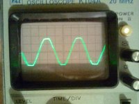
So I noticed that some of my transformers were getting warmer than expected, even when they were run quite below their specs. My trusty Lithuanian scope then revealed that my mains voltage looks a little (?) messed up, like a sinusoid with flattened tops and bottoms.
I now suspect that these flat parts lead to a partial saturation of the cores and thus heating occurs.
So my questions are: How bad, in comparison, is my mains voltage? And what can be done to rectify (lol, pun) the situation?
This: Mains DC and Transformers will only address a DC offset, right?
Additional info:
Here in Austria we have 230VAC 50Hz mains.
The first pic is the 15VAC secondary of a small transformer (in my DCB1 build). The vertical resolution is 10V per unit.
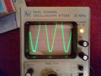
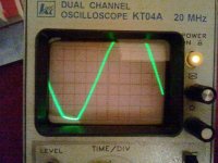
The second pic is the full monty, showing the 230VAC mains waveform (measured in a lamp socket...). The third pic is the same in greater detail. The vertical resolution in the latter two pics should be 100V per division.
I now suspect that these flat parts lead to a partial saturation of the cores and thus heating occurs.
So my questions are: How bad, in comparison, is my mains voltage? And what can be done to rectify (lol, pun) the situation?
This: Mains DC and Transformers will only address a DC offset, right?
Additional info:
Here in Austria we have 230VAC 50Hz mains.
The first pic is the 15VAC secondary of a small transformer (in my DCB1 build). The vertical resolution is 10V per unit.
The second pic is the full monty, showing the 230VAC mains waveform (measured in a lamp socket...). The third pic is the same in greater detail. The vertical resolution in the latter two pics should be 100V per division.
Attachments
Not an uncommon situation. The reason for the flat-topping is a large percentage of the load consists of capacitor input DC power supplies. Just about anything electronic in your house (as well as your neighbor) has this type of power supply. These power supplies draw current in pulses near the peaks of the sine wave. With most load being drawn at these peaks, it effectively causes voltage drop only at the peaks, and the result is what you see on your scope.
In the US, ANSI/IEEE standards are adopted by the Public Service Commission, which states 5% THD or lower on the voltage. You likely meet this 5% spec, so there may not be much the utility is willing to change. Not sure what your local requirements are. I wouldn't expect your transformers to be so unhappy with this waveform, however. What is the true-rms of your voltage? In truth, as long as your peak voltages are within reason, most DC power supplies really like this flat topping; it forces the current consumption to be less peaked, with lower crest factors. Ever run a DC power supply off a stepped sine inverter? They actually run quite well. Now for audio equipment there may be some noise issues to contend with, and your peaks are probably not where they should be, but I would think this a minor issue.
What else can be done: unfortunately, not much other than maybe a ferroresonant transformer, which carries its own set of cons. Recreating a sine wave is not a simple task.
Most of the concern about DC on the mains is unfounded IMO. Unless you have a half-wave rectified water heater (unlikely) you probably have little to no DC. Remember you are fed from a utility transformer nearby.
And that transformer is fed by the local substation which has plenty of juice. I have seen worse looking mains than that on my scope. I once discovered my mains was too high by playing with my little audio stuff. The mains measured 138VAC which is pushing out of spec. I filed a complaint and apperently there used to be another building fed with the local transformer and it was now empty. They sent a crew to change the tap on the local transformer primary, and just for fun here, which way would they move the primary tap to lower the voltage?
I once discovered my mains was too high by playing with my little audio stuff. The mains measured 138VAC which is pushing out of spec. I filed a complaint and apperently there used to be another building fed with the local transformer and it was now empty. They sent a crew to change the tap on the local transformer primary, and just for fun here, which way would they move the primary tap to lower the voltage?
Last edited:
The clipping of the sinewave indicates the addition of lot's of harmonic. It is not an indication of DC.
The extra harmonics if below that 5% distortion value will lead to a little extra heating.
If the harmonics content increases then the heating effect will increase.
50/60Hz transformers are not designed to tolerate much of 150/180Hz and 250/300Hz and 350/420Hz and etc.....
I am away out in the country and my waveform looks like that. The number of industrial consumers and miscellaneous customers between me and the nearest generating plant could be millions.
Last edited:
I never seen anything like that.
Are you in a residential area or are there industrial units and so on around ? Whats it like through the night/early morning ?
It was an older apartment complex that was sharing the same transformer with another complex building. The other went dark, as in condemned, so the load became very light on such a big transfo.
Last edited:
I wouldn't get too concerned about it.
Just wait until the ban on those evil, demon-possessed, earth-destroying incandescent light bulbs comes full circle, and we are all squinting under fluorescent lights. Then you'll see what harmonics do to a power system.
http://www.pge.com/includes/docs/pd...rvice/energystatus/powerquality/harmonics.pdf
Note also that it isn't so much the voltage harmonics that require derating a transformer, it's the current harmonics. Those are 95% dependent on your amplifier, not the house voltage. So a slightly flat-topped voltage will not drastically affect the operating point of your transformers. In fact, since the volt-second product has gone down, I would say your losses are less than they would be for a perfect sine wave.
Last edited:
I live in an apartment complex in a medium/small town (see pic) and there shouldn't be any large industrial units around. The pics were taken around 17:30 today. I'll get some comparable shots at various times of the day, maybe there is some sort of correlation.
The voltage checked out fine at 230Vrms when I took the pics.
Would the circuit in Figure 8 in the link I posted in the first post do any good in my situation?
The voltage checked out fine at 230Vrms when I took the pics.
Would the circuit in Figure 8 in the link I posted in the first post do any good in my situation?
Attachments

Here is a similar thread on a electricians and NEC forum.
Flatened top sine wave, does it mean anything?
Flatened top sine wave, does it mean anything?
You could put a mains filter on the front of anything that might take offence to harmonics.
An externally hosted image should be here but it was not working when we last tested it.
It was an older apartment complex that was sharing the same transformer with another complex building. The other went dark, as in condemned, so the load became very light on such a big transfo.
Thanks... see what you mean about which way to alter the taps.
It would be interesting to see how the problem lessened as you worked back down the distribution chain.
Nigel that posted filter design needs review.
The two Y-caps are far, far too large. 2u2 passes about 170mA on 240VAC and will open the MCCB instantly.
More seriously, Y-caps are limited by consideration of the shock hazard in the case of a fault with the mains or appliance earth connection. That alone means a maximum of about 4n7 each is permitted (limiting the earth leakage to 0.3mA - a fair sting, but not fatal).
Edit to add: and with 9uF between the L&N phases, the 1meg resistor is far too large to pull-down the peak stored voltage fast enough to prevent a shock hazard if the thing is accidentally unplugged! Something closer to 22K (meaning a constant 2.5w of dissipation) would be better.
HTH.
Last edited:
Thanks for the links, very interesting! I'll fully read through it tonight if I find some time.
From what I can tell the waveform seems to always looks like that, it at least did when I was looking at it at 1am, 10am, 2pm, 5pm and 10pm.
And 9µF between L&N sounds uncomfortably large.
From what I can tell the waveform seems to always looks like that, it at least did when I was looking at it at 1am, 10am, 2pm, 5pm and 10pm.
And 9µF between L&N sounds uncomfortably large.
the maximum earth leakage current on an RCCB monitored circuit is limited to <=25% of the earth leakage rating.Y-caps are far, far too large. 2u2 passes about 170mA on 240VAC ....................... and with 9uF between the L&N phases, the 1meg resistor is far too large ...........
For the commonly used domestic RCCBs @ 30mA, this limits the total leakage from all equipment on that monitored circuit to <=7.5mAac
If there were 10pieces of equipment on that circuit then the total Y capacitance is ~90nF and that leaves very little wiggle room for any individual piece of equipment to use as much as as one would like for interference attenuation.
The L to N capacitance is ~5u5F and 100k would reduce the peak stored voltage to <20Vpk in ~2seconds after pulling the plug, (one RC is ~500ms).
Dissipation is down to <600mW. If that's too high, then adopt 220k
I don't know, but from what I have garnered over the decades, I think not.Isn't there also a safety limit on earth current of 1mA per item?
Medical equipment have an alternative set of rules.
Intrinsically safe equipment are governed by alternative rules.
etc.
- Status
- This old topic is closed. If you want to reopen this topic, contact a moderator using the "Report Post" button.
- Home
- Amplifiers
- Power Supplies
- How bad is the quality of my mains voltage and what can I do to improve it?