+1 Weems book recommends a percentage overvolume, cant recall exactly what that is, but in my last project i used an overvolume of 30% which worked well. In the end i cut around an inch off port length, which brought the tuning back almost exactly. If in doubt id follow a similar route.Unless you can find a driver with horizontal TS curves, there is no such thing as accurate tuning of a BR.
Further driver to driver variation on really good drivers typically varies +/- 10% making life even harder.
To me it makes sense to do vented systems that have a high tolerance to dynamically changing parameters.
dave
As usual, this thread has gone every which way (something I personally love about this forum), but I might point to Sreten's answer as the most cogent.
To simplify, I say do a box sim of your design and look at the 'knee' of the response. The sharper the knee, the more sensitive the design will be to dimensional variations.
To simplify, I say do a box sim of your design and look at the 'knee' of the response. The sharper the knee, the more sensitive the design will be to dimensional variations.
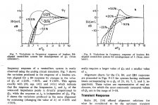
Here is an answer in graphical form from the Dick Small vented box paper. The left graph shows variation due to changes in Qt and the right curve shows variation in h, the fb/fs ratio. (So tuning error is h error). You can see for the case given (lossless B4 or 4th order Butterworth) you get a band edge error of about 1 dB for every 10%.
Regards,
David
Regards,
David
Attachments
+1 Weems book recommends a percentage overvolume, cant recall exactly what that is, but in my last project i used an overvolume of 30% which worked well. In the end i cut around an inch off port length, which brought the tuning back almost exactly. If in doubt id follow a similar route.
You miss the most important point made: change the level from that at which you have tested with to get the tuning "right" and the tuning will now be off because the driver parameters have changed.
dave
you get a band edge error of about 1 dB for every 10%.
So if you consider that static T/S can be on the order of +/- 10% and dynamic changes even more....
dave
Not to be too pedantic but box Q is meant to mean the Q related to box losses (along with vent Q). Q loss is usually down to leakage and also stuffing losses. Small did his paper with an assumption of a box Q of 7 (not 0.7).
You are referring to a system Q n the region of 1 or less. Unfortunately that isn't correct either as we would be considering a 4th order system, so the Qs that would apply to a 2nd order system (Butterworth = Q of 0.7) don't apply either. A 4th order Butterworth has 2 Qs, one of 0.541 and one of 1.31.
We discussed this previously, but I don't think you grasped it then.
http://www.diyaudio.com/forums/multi-way/176992-4th-order-butterworth-filter-q-2.html#post2360525
David S.
Actually, Small is the one who identified the loss factor for the boxes and showed how the typical loss varies with size and construction. His loss factor is what made N.T's work actually translate to the real world. Do not confuse his loss factor with system Qts, the value we suggest is best around .6 for a sealed box. I might refer everyone to the original Bullok papers published in Speaker Builder where he made sense, and even provided useful compensated charts to use.
Obviously, a ported box will have two resonance peaks, one for the driver and one for the box. It is typically the driver in-system we look at, not the port Q.
Don't forget, T/S parameters vary widely with the power they are measured at. Try it. Measure at 1mW, then at 1W and again at 10W. There is no standard.
Don't believe temp matters? Measure one stone cold. Play it loud for a while and measure again. Between the difference in Re and Qms, you can get more than 10% variance. Everyone should try this.
Don't believe temp matters? Measure one stone cold. Play it loud for a while and measure again. Between the difference in Re and Qms, you can get more than 10% variance. Everyone should try this.
The T/S parameters may shift with drive voltage but the physics of the neck coupling to the volume (port Q) is basically stable (given that air density/pressure changes will affect the coupling a bit). The efficiency of the driver to couple to the volume is what changes with the T/S shift.
edit: unless the port is undersized for max SPL around Fb, then it will shift down in frequency with increased voltage / air velocity .
edit: unless the port is undersized for max SPL around Fb, then it will shift down in frequency with increased voltage / air velocity .
Last edited:
I have no idea what you are talking about neck coupling. Sounds dirty.
A Helmholtz resonator has two parts, the volume of air in the chamber, and the neck (port) and its air volume and associated resonances depending on opening area and length. The volume of air in the neck (port) couples to the vibrating air in the chamber more efficiently the closer the chamber's vibrations come to the Fp. Above this (port) frequency range the port acts as a air plug and the box acts just like a sealed box. Any port output graph will show this. Sorry it's not very naughty, actually kinda boring.
edit: http://people.seas.harvard.edu/~jones/cscie129/nu_lectures/lecture3 /ho_helmholtz/ho_helmholtz.html
Last edited:
But that tells you or the room nothing about what Qbox is. Is Qbox ~0.6, or 0.7, or 0.8, or 0.9, or 1.0, or good God, I hope you don't aim for Qbox>1.0
I hate high Q boxes. They never sound "right" on a wide range of music and voice.
I prefer lower Q and fairly recently discovered that low Q boxes can also sound quite accurate.
Hi Andrew,
Just saw your post here, just about to build some reflex cabinets.
Could you say what Q value you prefer in reflex boxes to achieve the "right" sound.
many thanks
mike
I don't know how to measure the Q of a reflex, but I do know what a low or medium Q looks like when doing a plot.
Someone suggested I aim for Q=0.5 for my build so I played with values in Winisd pro until the shape looked like a Bessel over the roll-off range of frequencies.
When I got that built it did indeed sound nice and truthful (male voice now sounded right). And it went way deeper than the previous box (Tannoy B950).
All I did was weight the moving cone until I got Qts higher, that suited the Winisd value and blocked off one of the two ports. That increased the box size slightly and lowered the tuning a lot.
This massively reduced the sensitivity, but it was already specified >100dB/2.83V @ 1m
Keep in mind the 29 liters is working internal volume, not cabinet volume. You need to make a best guess estimate of your driver's physical volume and subtract that from the cabinet.
Though there are various way of doing this for cone drivers.
Someone suggested a quick and easy means by simply using the volume of a cylinder to calculate the magnet.
Then measure the cone from inner edge of the surround to inner edge of the surround, estimate the angle and height of the theoretical full geometric cone, then calculate the volume of the resulting cone.
Add the two together and you have a fair approximation of the driver's displaced volume.
Calculate this value for each driver then subtract it from the total internal cabinet volume to get the working internal volume.
If you are building cabinets, then need to be that much larger to get the working cabinet volume you want, or you have to re-tune the port to get the resonance frequency you want.
There are Port Tuning Calculators on the Internet. Here is one from the same people (Linear Team) who wrote "WinISD" -
LinearTeam - Port Length Calculator
To the extent possible, use the actually internal volume of the cabinet, then find the right port tuning.
I have a cabinet of about 2.5 ft³ with a 12" driver which I estimated at about 0.5 ft³.
If we assume a 40 hz tuning frequency, here are the difference in the port, when the cabinet is adjusted for actual internal volume vs cabinet volume -
Cabinet volume = 2.5ft³, Tuning 40hz, 1 port 3" in diameter -
Port Length = 2.55 inches
Cabinet volume = 2.0ft³, tuning 40hz, 1 port 3" in diameter -
Port Length 3.71 inches long
If I use the working 2.0 ft³ and calculate the frequency at which a 2.55" port will resonate, to see how far the tuning frequency shifts, I get -
44.6hz = 2.555"
Whether that is enough to matter to you or not, is up to you to determine.
For reference -
2 ft³ = 56.6 liter
2.5 ft³ = 70.8 liter
A single 8" bass driver of roughly 0.2 ft³ = 5.7 liters.
Not knowing your drivers and their geometric volumes, the best I can do is use my own speakers as an illustration.
My point is, you can not assume the generic cabinet volume, you need to subtract the volume of the drivers and use the working volume of the cabinet to calculate the port.
Also Flared ports are going to be a couple inches longer because only a small part of the flare is included in the Duct Length.
Steve/bluewizard
Last edited:
I don't know how to measure the Q of a reflex, but I do know what a low or medium Q looks like when doing a plot.
Someone suggested I aim for Q=0.5 for my build so I played with values in Winisd pro until the shape looked like a Bessel over the roll-off range of frequencies.
When I got that built it did indeed sound nice and truthful (male voice now sounded right). And it went way deeper than the previous box (Tannoy B950).
All I did was weight the moving cone until I got Qts higher, that suited the Winisd value and blocked off one of the two ports. That increased the box size slightly and lowered the tuning a lot.
This massively reduced the sensitivity, but it was already specified >100dB/2.83V @ 1m
Thanks Andrew,
I think we agree on this issue - as it happens I don't like the sound of High Q resonance anywhere in the audio chain - but I have yet to establish how low it has to be in speaker cabinets to please my ears . . . but think a bessel roll off is a good place to start.
mike
Last edited:
Just to clarify a persistent misunderstanding:
If we talk of sealed boxes which are a 2nd order system then there is only one Q for the system. We recognize a Q of 0.5 as being moderately low with a rounded corner. A Q of 1.0 gives a dB or so of peak and a squarer corner.
We can not apply the same terms to a vented box because it is not 2nd order. It is 4th order so it has 2 Qs required. They will not be ".6" or similar!
For example, a 4th order Butterworth has 2 Qs, one of 0.541 and one of 1.31. Although a section has a Q well above 1.0, the end result is what is termed as maximally flat and has a fairly low ringing factor. Anyone that terms a vented box as "Q of 0.5" (or 0.6) is forgetting that it is a 4th order system.
Do a google search of Butterworth coefficients and you will see that a higher order filter requires a broad range of mathematically derived Qs.
David S.
Hi David,
Thanks for your input. You clearly have a very thorough knowledge of complex filters - certainly more than mine . . . but never-the-less, even though the language we use might be almost offensively vague to you, hopefully you know what we mean what we say that a reflex speaker can sound "tighter" in the bass if one tunes down the classic "maximum inband bass without ringng" butterworth approach and creates a more gengle roll off.
Even without the details of the math it really isn't too complicated . . . with winisd or simliar & a computer measurement suite, it's relatively simple begin with the classic butterworth type design and by tweaking the box size & port length achieve something a bit better damped and get a really great result.
Wouldn't want to put anyone off by making it sound too complex.
cheers
mike
Last edited:
- Status
- This old topic is closed. If you want to reopen this topic, contact a moderator using the "Report Post" button.
- Home
- Loudspeakers
- Multi-Way
- How accurate does bass reflex tuning need to be?