Not quite; to be an SRPP there would either have to be a coupling capacitor in there, or the resistive load would have to be returned to a fixed potential that is equal to the upper cathode voltage i.e., so there is no quiescent DC in the load resistor.
As it is, current can only flow in one direction in the load.
As it is, current can only flow in one direction in the load.
I covered this type of stage in my article (see half-mu amp)
Where can we find the article?
Cheers
audioXpress May 2010 "The Optimized SRPP Amp, Pt 1", Merlin Blencowe
audioXpress June 2010 "The Optimized SRPP Amp, Pt 2"
Glass Audio V.12, #3, 2000 "SRPP's Harmonic Cancellation Capabilities", Stefano Perugini
These articles are good in explaining the basics of the tubes SRPP, and will be useful for transistors users too.
audioXpress June 2010 "The Optimized SRPP Amp, Pt 2"
Glass Audio V.12, #3, 2000 "SRPP's Harmonic Cancellation Capabilities", Stefano Perugini
These articles are good in explaining the basics of the tubes SRPP, and will be useful for transistors users too.
Hi, I use a SRPP as a line stage and as said by others before it sonically is very transparent.
In my case, using the 6922 with the cathode grounded, and variable DC bias on the grid (yes, and a coupling cap! yikes!). I have 4 of these in parallel for each channel, and since this gives me way too much gain I threw in a output transformer 4:1.
It sounds very nice, I can even hook up a headphone straight into the output and it works beautifully. Next build will be RTP5, and a separate headphone amplifier though.
Thank you. I just read it on ValveWizard, what a great website....
Ditto, a very good article, I think I read that before but did not appreciate the technical lack of push-pull when you take the cap out.
I guess you have some push-pull action when driving heavy miller capacitance fast on a triode gate though?
My own use of SRPP is into a pentode gate, so one day I'll load up the SRPP with a resistor to drop the distortion. Out of all the driving stages I tried for the GU50 (both triode strapped and pentode mode) though it was the one I liked the sound of best, the way I'd describe it is clear, interesting and effortless.
Perhaps this comes from the effect of eliminating some of the triode differences (it relies on mu only), the high gain and the huge swing - making the distortion for the actual output voltage swung very low. Also when it does hit some load it really doesn't notice because the top tube can pull harder than a common-cathode resistor when it needs to.
Also I like the SRPP because it's very simple, dead easy to wire up and saves a big resistor (as you change that for a big 'self cooling' tube
") )
)I must respectfully disagree on the point of DC coupling negating push-pull operation of the SRPP circuit. My analytic models, simulations, and actual circuit measurements on DC coupled class A2 and class B amplifiers with quiescent grid current suggest otherwise.
Push pull operation means both the bottom triode and the top triode are able to source signal (AC) current into the load, correct?
How does adding or subtracting some DC current into the top triode cathode branch change the AC operation at all, unless the top triode gets driven into saturation or cutoff?
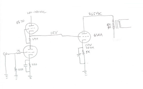
Taking in particular the SRPP Loftin-White schematic presented, the designer was apparently careful to return the 390K resistor to approximately the same voltage as the quiescent op point of the SRPP, thus little or no DC current is injected into the SRPP.
Certainly the signal current through the 390K is small, but some of it is inevitably sourced by the top triode, no?
Cheers,
Michael
Push pull operation means both the bottom triode and the top triode are able to source signal (AC) current into the load, correct?
How does adding or subtracting some DC current into the top triode cathode branch change the AC operation at all, unless the top triode gets driven into saturation or cutoff?
Taking in particular the SRPP Loftin-White schematic presented, the designer was apparently careful to return the 390K resistor to approximately the same voltage as the quiescent op point of the SRPP, thus little or no DC current is injected into the SRPP.
Certainly the signal current through the 390K is small, but some of it is inevitably sourced by the top triode, no?
Cheers,
Michael
Hmm, I was thinking that there was DC across that resistor, but on closer inspection I think you may be right about this schem!Taking in particular the SRPP Loftin-White schematic presented, the designer was apparently careful to return the 390K resistor to approximately the same voltage as the quiescent op point of the SRPP, thus little or no DC current is injected into the SRPP.
I must respectfully disagree on the point of DC coupling negating push-pull operation of the SRPP circuit. My analytic models, simulations, and actual circuit measurements on DC coupled class A2 and class B amplifiers with quiescent grid current suggest otherwise.
Push pull operation means both the bottom triode and the top triode are able to source signal (AC) current into the load, correct?
Yes, you are correct. SRPP action has nothing to do with the presence/absence of the "cap". You just need to design SRPP.
That is not quite true. The load is fundamental to the operation of the SRPP. If, for example, you directly coupled the 'SRPP' to the grid of another valve then it is no longer an SRPP because there cannot be any push-pull action.Yes, you are correct. SRPP action has nothing to do with the presence/absence of the "cap". You just need to design SRPP.
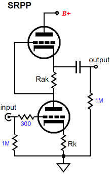
e.g:This is an SRPP:
This is NOT an SRPP:
An externally hosted image should be here but it was not working when we last tested it.
This is NOT an SRPP either:
SRPP is acting push-pull in the sense the lower and the upper gain elements change their internal impedance in the opposite direction. It can be considered as a variable attenuator. In AC operation, the source impedances of the upper and lower gain element are connected parallel. This resulting source impedance has a maximum at no signal, and is symmetrically decreasing with signal in either direction. (For example in steady state 10k + 10k results 5k, in the +ve half peak 5k +15k results in 3.75k, same for the -ve peak; now you see what I mean). The load is just in series with this source impedance.
Therefore the SRPP has symmetrical output current (via a capacitor into a load), but it has also symmetrical output voltage even without any load. This is because the above mentioned attenuator (comprising of dynamically controlled gain elements) changes its upper and lower impedance symmetrically.
Therefore the SRPP has symmetrical output current (via a capacitor into a load), but it has also symmetrical output voltage even without any load. This is because the above mentioned attenuator (comprising of dynamically controlled gain elements) changes its upper and lower impedance symmetrically.
It's always a puzzle to me, how things work (with human perception). After reading Merlin'sarticle (some time ago), I said to myself "At least he understand SRPP basics". And now I am reading your posts here...
Let's put things in perspective. There are three variations of a "serial amplifier of SRPP topology": SRPP, Mu-Follower, and amplifier with "Dynamic Load". Dynamic load means non-linear resistance, not a CCS. And that is, typically, triode. All three do look similar and can exibit a smooth transition from one mode of operation to another, depending on the nature/combination of the galvanic Link between the active devices, load, active devices themselves, bias.
The second pic in post 31 clearly is not a SRPP (variety - no SR !) at all ! It can be described as DL, though. Pic 1 is SRPP, but it can be described also as DL, depending on the conditions I have listed, namely: if the amplitude of AC current into the load will be miniscular in comparison with the bias current. But it has nothing to do with the depicted cap, unless it is so small, that it will increase the impedance of the stage load (1M plus iwC). Pic 3 is the opposite of pic 1, because it is DL, transitioning into SRPP with the frequency rise. So, posters Michael, Globulator, oshifis are correct in this regard, (count me in), because we cannot limit ourselves only to DC domain, when analyzing the circuits, that analysis also need to include the HF behavior (and transient response, if you want...). And that HF behavior will be affected by any capacitance (Input/Miller, MOSFET gate, RIAA network, cable...), or inductance, if any present. So, in the quote: <<Yes, it does deliver push pull into the Miller capacitance. Now we are getting pedantic>> second sentense has nothing to do with the reality. So, should we say more?
A few words for those, who can hear (unrelated to the stambling blocks in this thread discussion). In the SRPP (mode, sufficient current into the load), as depicted in pic 1, as an example: BOTH active elements are connected in parallel on AC as COMMON SOURCE triodes, There is local feedback (Rk) on the bottom one, but there is very little FB through Rak for the top one. The amount of local FB for the top triode will depend on the output impedance of the bottom triode - if the bottom active element will be pentode, local FB through Rak for the top triode will disappear. Top's Rak will act as a FB only in DL mode (load current is unsignificant vs. bias).
P.S. Oh, what the hell... Here the web links to the articles I've mentioned before:
This website is frozen.
Non Linear Behaviour of Shunt Regulated Push-Pull @ PAEng
The Totem Pole Amplifier Paragraph Taub&Millman, Pulse and Digital Circuit, Cap.3, Linear Pulse Amplifiers, pp. 99-101, McGraw-Hill, 1956. @ PAEng
Clarification:
In my statement:
"BOTH active elements are connected in parallel on AC as COMMON SOURCE triodes"
I meant COMMON CATHODE - Mosfets were flying through my head at the moment...
And I used "iwC" to refer to "capacitor impedance", not the precise formula to
calculate it.
In my statement:
"BOTH active elements are connected in parallel on AC as COMMON SOURCE triodes"
I meant COMMON CATHODE - Mosfets were flying through my head at the moment...
And I used "iwC" to refer to "capacitor impedance", not the precise formula to
calculate it.
- Status
- This old topic is closed. If you want to reopen this topic, contact a moderator using the "Report Post" button.
- Home
- Amplifiers
- Tubes / Valves
- How a SRPP stage sounds like?