deandob said:Yes, the LM4562 can be swapped in but the CRD's need to be connected to the positive supply, not the negative supply as per the CRD connections on the circuit board. You can cut the tracks and hard wire them to suit (dont forget to reverse the orientation of the CRD).
Add tantalum caps about 4.7uf to both supply rails of the opamp, soldered across the opamp supply pins or close by.
Regards,
Dean
Dean,
Do you have a picture of your UCD 400 showing the mounted LM4562 opamp mounted with the CRD on the + rail?
Thanks in advance.
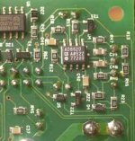
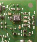
Photos of my 1/2 built UCD amp showing the CRD and LM4562 mods.
If anyone is interested in the specs for this 5 channel amp:
- 2 x UCD 400 with CRD power supply mods & LM4562 opamp with tantalum power decoupling & CRD mod (+ve rail which means I had to hack the circuit board to make it fit). Also has Panasonic FC caps and replaced the output filter with 2 x 330nF MKT caps.
- 3 x UCD180 with OPA2134 opamp, MKT output filter and Panasonic FC caps, CRD on the power supply but not on the OPA.
- L + R channel have dedicated supplies, each has a 300VA toroid with Schottky rectifiers, dual bridges per rail and T-Network 10,000uf caps.
- Center + 2 x rear have a shared supply with 300VA toroid + 10,000uF slit foil caps, dual schottky rectifiers
- Input for 3 x unbalanced + 2 x balanced inputs
- 5 channel relay shunt volume control
- Input & volume controlled by a microcontroller that is connected to a PC via USB. This amp is for a dedicated home theater PC which has an EMU 1820m soundcard for analog outputs connected to this amp (as well as TDA1541 NOS DAC). The PC will control the output and volume of the amp and I might also add IR control also.
Regards,
Dean
Attachments
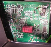
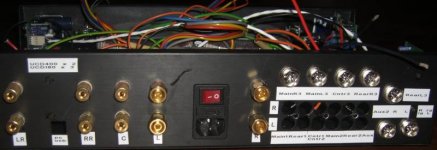
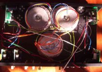
deandob said:Photos of my 1/2 built UCD amp showing the CRD and LM4562 mods.
If anyone is interested in the specs for this 5 channel amp:
- 2 x UCD 400 with CRD power supply mods & LM4562 opamp with tantalum power decoupling & CRD mod (+ve rail which means I had to hack the circuit board to make it fit). Also has Panasonic FC caps and replaced the output filter with 2 x 330nF MKT caps.
- 3 x UCD180 with OPA2134 opamp, MKT output filter and Panasonic FC caps, CRD on the power supply but not on the OPA.
- L + R channel have dedicated supplies, each has a 300VA toroid with Schottky rectifiers, dual bridges per rail and T-Network 10,000uf caps.
- Center + 2 x rear have a shared supply with 300VA toroid + 10,000uF slit foil caps, dual schottky rectifiers
- Input for 3 x unbalanced + 2 x balanced inputs
- 5 channel relay shunt volume control
- Input & volume controlled by a microcontroller that is connected to a PC via USB. This amp is for a dedicated home theater PC which has an EMU 1820m soundcard for analog outputs connected to this amp (as well as TDA1541 NOS DAC). The PC will control the output and volume of the amp and I might also add IR control also.
Regards,
Dean
Hi Dean
the output filter cap was already a MKT
To have an improvement , i think you must replace with MKP
Alain
Thanks Dean.
Question for a UCD 400AD:
1. I think I have read that the + & - opamp power rail decoupling caps are creamic surafce mount .1uf. Is this value correct?
2. Can those caps be totally replaced (in lieu of just bypassed) with a film cap like a Wima MKP2 which goes up to .33uf 250V with 5mm lead spacing?
Thanks in advance.
Steven,
Yes, they are 0.1uF ceramic SMD. IMO not sufficient given the distance from the regulator & the regulator design. Adding a higher value cap here should give the bass a bit more weight althought to be honest I did not try a before/after test. Yes, you could just replace them, especially if the combination of the ceramic 0.1uF and a higher value cap creates a resonant circuit with ringing (check this with a CRO).
Stephen,
You could do that also. Try it and see what you like better. Tweaking is pretty much to personal taste, and these modules are pretty good just standard so there is no right or wrong. There is plenty of info in this thread about what others have tried if you care to read back.
Regards,
Dean
The onboard opamp CRD has a different function to an auxillary supply and is not related, it biases the output transistors in the opamp into class A, removing cross over distortion. So you dont need to remove the onboard CRD in fact you should keep it there. If you are confused with my post above, it is because I have adjusted the UCD400 regulator design to include a CRD to provide a constant current to the regulator diode, which results in lower noise. The UCD400 regulator is a good design and with a bit of tweaking will come close to using an auxillary supply. But you should try both and see which configuration you like.
Regards,
Dean
Regards,
Dean
LM4562 vs. AD8620
I did the change to LM4562 an month ago and had a mixed feeling: after an hour of burning in, I was pleased with the more open mids and highs, the extreme transparency and the HF seemed to go unlimited. The ADs sounded more restricted, and as if just above 20kHz they would cut off. Not with the LMs. Most surprising was the low midrange, which had more presence and nice grain, making voices more palpable.
But the Bass was less weighted, almost recessed (although it was tight and articulated); on small speakers it sounded unsatisfying. Even some big speakers lack of weight in bass. Now, after almost a month, it seems to be better, even not perfect, but I don't regret the swap, and will probably work on the supply to get it better.
Definitively the best choice for the UcDs.
cheers
- dan
Stevenacnj said:BGT
2. What was the difference in sound quality between the AD8620 & LM4562 on your UCD 400?
Thanks in advance.
I did the change to LM4562 an month ago and had a mixed feeling: after an hour of burning in, I was pleased with the more open mids and highs, the extreme transparency and the HF seemed to go unlimited. The ADs sounded more restricted, and as if just above 20kHz they would cut off. Not with the LMs. Most surprising was the low midrange, which had more presence and nice grain, making voices more palpable.
But the Bass was less weighted, almost recessed (although it was tight and articulated); on small speakers it sounded unsatisfying. Even some big speakers lack of weight in bass. Now, after almost a month, it seems to be better, even not perfect, but I don't regret the swap, and will probably work on the supply to get it better.
Definitively the best choice for the UcDs.
cheers
- dan
Re: LM4562 vs. AD8620
I'd agree with that for sure sounds just like what I'm hearing here after changing the AD8620 to those LM4562's!
Alfetta87 said:
I did the change to LM4562 an month ago and had a mixed feeling: after an hour of burning in, I was pleased with the more open mids and highs, the extreme transparency and the HF seemed to go unlimited. The ADs sounded more restricted, and as if just above 20kHz they would cut off. Not with the LMs. Most surprising was the low midrange, which had more presence and nice grain, making voices more palpable.
But the Bass was less weighted, almost recessed (although it was tight and articulated); on small speakers it sounded unsatisfying. Even some big speakers lack of weight in bass. Now, after almost a month, it seems to be better, even not perfect, but I don't regret the swap, and will probably work on the supply to get it better.
Definitively the best choice for the UcDs.
cheers
- dan
I'd agree with that for sure
sounds just like what I'm hearing here after changing the AD8620 to those LM4562's!Yep. Same here. I'm looking for ways to get a little more presence in the bass, which I'm hoping I can tweak the source for. Let me know what you find.
Did you try additional 4.7uF supply decoupling caps near the opamp? It made a small difference in the bass weight.
Regards,
Dean
Did you try additional 4.7uF supply decoupling caps near the opamp? It made a small difference in the bass weight.
Regards,
Dean
deandob said:The onboard opamp CRD has a different function to an auxillary supply and is not related, it biases the output transistors in the opamp into class A, removing cross over distortion. So you dont need to remove the onboard CRD in fact you should keep it there. If you are confused with my post above, it is because I have adjusted the UCD400 regulator design to include a CRD to provide a constant current to the regulator diode, which results in lower noise. The UCD400 regulator is a good design and with a bit of tweaking will come close to using an auxillary supply. But you should try both and see which configuration you like.
Regards,
Dean
I was thinking to this: http://www.diyaudio.com/forums/showthread.php?s=&threadid=38199&perpage=10&highlight=&pagenumber=78
and specifically to those words from Bruno Putzey:
Precisely. If you have excellent supplies the difference goes away.
Balanced verses Unbalanced Wiring
I have an idea that if conceptually correct would include both RCA & XLR connections to the amp while providing offset protection for only the RCA & the internal wiring of the amplifer would remain the same regardless of the source type. So I would like to bounce my idea off of you.
Conceptually, if one were employing an unbalanced source they could connect to the amps RCA connector and if they had a balanced source they could connect to the XLR (No conversion cables and no external XLR terminators with pins shorted). The 3 wires from the internally mounted XLR connectors would go to the UCD Module which would have the decoupling caps removed and replaced with a jumper wire. So, with the balanced connection, there exists no decoupling.
However, when connecting the RCA to XLR inside the chassis, one could allow an external unbalanced RCA-to-RCA cable interface while providing protection for only the RCA side without adding the cap back to the UCD.
One would merely connect pin 2 of the RCA to pin 2 of the XLR with the appropriate capacitor instead of a jumper wire. Additionally, it may make sense to connect a high value resistor from the RCA’s Hot Pin to its ground Tab Connection (both at the RCA connector on the inside of the chassis). One could do this, in the odd chance that a large DC value was present at the Hot Pin, I believe this resistor would act as a “bleed off” device to allow the current to flow back to ground and lower the offset.
I was thinking of using perhaps a 3.3 uF Clarity Cap SA series high pass filter coupled to the input impedance of the op amp (about 100,000 ohms) yielding a cutoff frequency of 0.48 hertz. I am considering a 1 meg-ohm 1/8 watt metal film capacitor resistor for the bleeder function.
Please consider and let me know if this is viable.
Thanks!
douglask
- Status
- This old topic is closed. If you want to reopen this topic, contact a moderator using the "Report Post" button.
- Home
- Amplifiers
- Class D
- Hotrodding the UCD modules