About the Hotrodding issue, the one thing I am mostly concerned about is the PSU design/component. I am specially interested into comparative results of different powercaps and how they affect the UCD sound. There seems to be some information on the original UCD threads, but it is sparse and quite limited. The one thing I know is that BlackGate caps sound great acording to Bruno, but they're kinda of too expensive to most people. having people informing about the perceived performance, or even better, their testing experiences with FTcaps, BHC, BCVishay, Elna, Sikorel, Thel, Panasonic, etc would be quite usefull.
I am already looking for replacement DC deoupling caps for the signal, and the only recomendation I've got right now are the WIMA MKS2 2,2uF. I think it is a sure bet that these caps are quite critical to the final sound quality, and having comparisons done and described would be mostly usefull.
I am already looking for replacement DC deoupling caps for the signal, and the only recomendation I've got right now are the WIMA MKS2 2,2uF. I think it is a sure bet that these caps are quite critical to the final sound quality, and having comparisons done and described would be mostly usefull.
sx881663 said:
The Auricap I used was the 450 volt. It is about the same size as their 1uf @ 200v. The Auricap has quite heavy leads for this size of cap and correspondingly lower ESR. Not sure how much that would affect results. My only recommendation would be to use a cylindrical type for its better properties. Also a more precision piece would be nice. Generally higher voltage caps sound better but are bigger. It is necessary to fit the right compromise to the actual usage. I haven’t done the experiments yet but am getting more modules next week and am going to do extensive testing. I will post my results good or bad.
Roger
Roger,
I checked the dimensions and the Solen's are actually slightly larger than the Auricaps. But they do have thiner leads. I tend to prefer the sound of Auricaps though... The Panasonic aren't of the cylindrical type. I'll be doing the power supply caps first to assess their impact on the overall sonic presentation.
I'm looking forward to your results.
classd4sure said:Hi,
It's funny that this hot rodding thread is only thus far touching upon coupling caps.
Why look at the sine wave when it's the sound you should be concerned with, I'm not sure I'd even expect the look of the sine wave to change just by changing the coupling caps.
Someone should at least note that while removing or bypassing the coupling caps is an obvious and admitted improvement, they _are_ there for a reason, and that reason should be observed and respected, someone is likely to remove them expecting improved sound and blow their module..
Also this thread can never provide you or anyone with a "hotrodding" recipe as the final quality is a subjective experience..
With that in mind it may be more helpfull if more people posted what they have tried, and the results they've experienced, for example, instead of blindingly throwing the most expensive caps at it, find me a set of cheap caps that sound even better...
Regards,
Chris
Chris
Chris,
I'm not sure if there's that much things we can safely change on these modules except replacing or removing a few caps. The power supply of the amp I built was seriously tweaked though. My UcD400 sounded so good that I haven't had the urge to change anything in it.
Until I decided to attack the modules themselves by reading this thread and some of Bruno's recommendations.
You're right the caps are there for a reason, but if you can be certain that there's no DC going into your amp, they can be removed. For instance, I have a transformer based volume control passive pre that will block any DC. Most tube pre-amps have coupling caps at their output, so no DC voltages should be present.
Now if you must be cautious, you can just replace the electrolytics with film caps. They don't need to be of the "audiophile" type. I'm sure a good polypropylene film cap from Panasonic, Wima, Vishay, or any other industrial type will sound much better than what's in there, it won't cost much.
Here are some images of my UcD400 amp:
http://www.audiocircle.com/circles/...ame=gallery&file=index&include=view_album.php
Julien
Nice amp
Julien,
Now that is the way to achieve low ESR! Everyone please note the bleeder resistors, nice addition. Also note that the cap banks have an input and output to isolate the ripple current. This also is worth duplicating. Looks like a well thought out project and suspect it sounds wonderful. Should be a real good platform to do module changes and evaluate the results with. Obviously you will have to say enough at some point and enjoy some music. Amazing how these amps improve your musical enjoyment.
What storage caps are you using? I will have to bite the bullet and get a few of the Jensen wonder caps (4 pole) just to try otherwise I will wonder if I have the best sound. I draw the line with Black Gate, just way too expensive.
Roger
ninjanki said:About the Hotrodding issue, the one thing I am mostly concerned about is the PSU design/component. I am specially interested into comparative results of different powercaps and how they affect the UCD sound. There seems to be some information on the original UCD threads, but it is sparse and quite limited. The one thing I know is that BlackGate caps sound great acording to Bruno, but they're kinda of too expensive to most people. having people informing about the perceived performance, or even better, their testing experiences with FTcaps, BHC, BCVishay, Elna, Sikorel, Thel, Panasonic, etc would be quite usefull.
I am already looking for replacement DC deoupling caps for the signal, and the only recomendation I've got right now are the WIMA MKS2 2,2uF. I think it is a sure bet that these caps are quite critical to the final sound quality, and having comparisons done and described would be mostly usefull.
I think the tweaks which have the most impact with the UCD are the filter caps , then the buffer op-amp
A guy in Paris has tried a lot of filter caps on a Zappulse2.2se and said that the BlackGate 10.000/63 are greatly the best and are worth the money
in my experience , to summarize :
- Elna lp3j : too smooth
-BC 056 : nice but too bright
-Elna Cerafine : a lot of bass , a midrange with a lot of harmonics ( amazing when playing piano , violin ...)
-Epcos Sikorel 105 : fast , linear , maybe the most natural i've tried
alain
Hi Julien,
really nice amp and properly done. I see you attempted to isolate the ground from the chassis. Interesting. Where did you find the case? I am ready to start making my UCD based power amp but the case is stopping me since I dont seem to find an attractive one.
regards,
Greg.
really nice amp and properly done. I see you attempted to isolate the ground from the chassis. Interesting. Where did you find the case? I am ready to start making my UCD based power amp but the case is stopping me since I dont seem to find an attractive one.
regards,
Greg.
Re: Nice amp
Thanks for the kind words, Roger.
To me, the amp sounds pretty good, overall better than anything I had in my system. It reminds me a bit of a tube OTL amp but with the power and punch of a SS amp.
Except for a few parts (Kiwame and Mill resistors, and solid silver wire for the PS rails), I've only used industrial parts as to keep costs reasonable. Still, total cost of this amp was more than 1K... One day I might try replacing the bypass caps with Auricaps...
The main PS caps are Panasonic TSUP 6800uF/100V, and the film caps are Panasonic Polypropylene. They have very good specs. I don't have any testing equipment, so I can't tell you how the PS measures, but it shouldn't be that bad since the sound isn't.
The Jensen caps should sound great. It would be interesting to compare it with industrial parts and note the measured and perceived differences.
I might have to pay you a visit in CA...
Thanks Greg.
The chassis comes from Taiwan, but the US distributor is Ken (a very nice guy), here in the NYC area. You can get more information from his web site:
http://www.digitalanaloguediy.com/
The chassis model is the Entry 130 (130mm height). It's a very nice chassis, all aluminum, it includes the nice speaker terminals, RCA and XLR inputs, the all in one switch, and feet.
Hope that helps.
sx881663 said:Julien,
Now that is the way to achieve low ESR! Everyone please note the bleeder resistors, nice addition. Also note that the cap banks have an input and output to isolate the ripple current. This also is worth duplicating. Looks like a well thought out project and suspect it sounds wonderful. Should be a real good platform to do module changes and evaluate the results with. Obviously you will have to say enough at some point and enjoy some music. Amazing how these amps improve your musical enjoyment.
What storage caps are you using? I will have to bite the bullet and get a few of the Jensen wonder caps (4 pole) just to try otherwise I will wonder if I have the best sound. I draw the line with Black Gate, just way too expensive.
Roger
Thanks for the kind words, Roger.
To me, the amp sounds pretty good, overall better than anything I had in my system. It reminds me a bit of a tube OTL amp but with the power and punch of a SS amp.
Except for a few parts (Kiwame and Mill resistors, and solid silver wire for the PS rails), I've only used industrial parts as to keep costs reasonable. Still, total cost of this amp was more than 1K... One day I might try replacing the bypass caps with Auricaps...
The main PS caps are Panasonic TSUP 6800uF/100V, and the film caps are Panasonic Polypropylene. They have very good specs. I don't have any testing equipment, so I can't tell you how the PS measures, but it shouldn't be that bad since the sound isn't.
The Jensen caps should sound great. It would be interesting to compare it with industrial parts and note the measured and perceived differences.
I might have to pay you a visit in CA...
greg filip said:Hi Julien,
really nice amp and properly done. I see you attempted to isolate the ground from the chassis. Interesting. Where did you find the case? I am ready to start making my UCD based power amp but the case is stopping me since I dont seem to find an attractive one.
regards,
Greg.
Thanks Greg.
The chassis comes from Taiwan, but the US distributor is Ken (a very nice guy), here in the NYC area. You can get more information from his web site:
http://www.digitalanaloguediy.com/
The chassis model is the Entry 130 (130mm height). It's a very nice chassis, all aluminum, it includes the nice speaker terminals, RCA and XLR inputs, the all in one switch, and feet.
Hope that helps.

greg filip said:Julien,
thank you for the link. The chassis does look nice; you would not happen to know if they got any distributors in Europe or have the url of the Taiwan site?
Greg.
Greg,
Try these:
http://www.my3c.net/
http://diyzone.net/index.php
You might want to contact Ken anyway. I'm sure he can arrange shipping to the UK directly from Taiwan.
Hope that helps.
Re: Re: Nice amp
These chassis look great, just would like to have them without all the connectors at the back. The 100mm heigh (or 80mm heigh would be nicer if it exists) version would be nice for my 3-channel amp (need to built two, one for each speaker). So I need more binding posts and more XLR connectors.
Any idea whether there are versions without all the connectors?
Best regards
Gertjan
Julien_M said:
Thanks for the kind words, Roger.
To me, the amp sounds pretty good, overall better than anything I had in my system. It reminds me a bit of a tube OTL amp but with the power and punch of a SS amp.
Except for a few parts (Kiwame and Mill resistors, and solid silver wire for the PS rails), I've only used industrial parts as to keep costs reasonable. Still, total cost of this amp was more than 1K... One day I might try replacing the bypass caps with Auricaps...
The main PS caps are Panasonic TSUP 6800uF/100V, and the film caps are Panasonic Polypropylene. They have very good specs. I don't have any testing equipment, so I can't tell you how the PS measures, but it shouldn't be that bad since the sound isn't.
The Jensen caps should sound great. It would be interesting to compare it with industrial parts and note the measured and perceived differences.
I might have to pay you a visit in CA...
Thanks Greg.
The chassis comes from Taiwan, but the US distributor is Ken (a very nice guy), here in the NYC area. You can get more information from his web site:
http://www.digitalanaloguediy.com/
The chassis model is the Entry 130 (130mm height). It's a very nice chassis, all aluminum, it includes the nice speaker terminals, RCA and XLR inputs, the all in one switch, and feet.
Hope that helps.
These chassis look great, just would like to have them without all the connectors at the back. The 100mm heigh (or 80mm heigh would be nicer if it exists) version would be nice for my 3-channel amp (need to built two, one for each speaker). So I need more binding posts and more XLR connectors.
Any idea whether there are versions without all the connectors?
Best regards
Gertjan
Chassis
ghemink
I have ordered mine from the link below, haven't actually seen them yet but thought you might want to check them out. They are heavy enough to serve as the modules heat sink and hold the transformer as well. No holes so you can do it any way you want.
Roger
http://www.iagaudio.com/products.asp?id=4
Re: Re: Re: Nice amp
Gertjan,
Here's are a few links to the chassis I was contemplating before I found out about the one I used:
http://www.par-metal.com/index.htm (they can punch holes and/or silkscreen if you provide them with a template)
http://www.thlaudio.com/
Hope that helps.
ghemink said:
These chassis look great, just would like to have them without all the connectors at the back. The 100mm heigh (or 80mm heigh would be nicer if it exists) version would be nice for my 3-channel amp (need to built two, one for each speaker). So I need more binding posts and more XLR connectors.
Any idea whether there are versions without all the connectors?
Best regards
Gertjan
Gertjan,
Here's are a few links to the chassis I was contemplating before I found out about the one I used:
http://www.par-metal.com/index.htm (they can punch holes and/or silkscreen if you provide them with a template)
http://www.thlaudio.com/
Hope that helps.
sx881663 said:
You may be able to jumper out the original 22uf caps in the 180 but watch the output DC. I would say if it is over .1 volt you will have to do something about it, like replace the opamp with one that has lower offset and bias current. After you jumper them out you can use rather modest size coupling caps between the modules input and the input jack. Most have settled on 2.2uf @ 200V for the best all around performance and safety.
If using input caps from the RCA’s put a 100k ohm metal film resistor across the RCA jack to insure any stored charge is dissipated.
Why is original cap 22uF if 10x smaller value is ok?
How can FR low limit calculated when using different sized caps?
What would be good size of the input caps in my Orions tweeter amp (>1440Hz ), and midrange amp (>100Hz)?
PS. I think i am using AudynCap polypropylenes what i have in hand many diffent sizes.
PS2. I have ordered 4pcs. 10.000uF 63V Aerovox T-Power 4 pole capacitors to my UCD180 dual mono power supply. Interesting to hear what will be diffence compared to current Rifa PEH200 sound.
Pasi P said:
Why is original cap 22uF if 10x smaller value is ok?
How can FR low limit calculated when using different sized caps?
What would be good size of the input caps in my Orions tweeter amp (>1440Hz ), and midrange amp (>100Hz)?
PS. I think i am using AudynCap polypropylenes what i have in hand many diffent sizes.
PS2. I have ordered 4pcs. 10.000uF 63V Aerovox T-Power 4 pole capacitors to my UCD180 dual mono power supply. Interesting to hear what will be diffence compared to current Rifa PEH200 sound.
Pasi,
The original UcD180 had the coupling caps on the output of the opamps going into a rather low impedance. This required a larger cap keep the lower frequency limit reasonable. The new circuits have the coupling caps on the input going into 100k ohm resistors. With this value a 2uf cap will give a 3db point around 2 Hz. Certainly this is low enough for anyone. I suspect the 22uf caps were just a carry over and do no harm being large.
Check out the link below to learn about coupling caps and how to do the calculations yourself. You will have to know the input resistance of your amps to do this.
I will have to look into the 4 pole caps you mentioned, look interesting.
Roger
http://www.st-andrews.ac.uk/~www_pa/Scots_Guide/experiment/highpass/hpf.html
sx881663 said:
Pasi,
The original UcD180 had the coupling caps on the output of the opamps going into a rather low impedance. This required a larger cap keep the lower frequency limit reasonable. The new circuits have the coupling caps on the input going into 100k ohm resistors. With this value a 2uf cap will give a 3db point around 2 Hz. Certainly this is low enough for anyone. I suspect the 22uf caps were just a carry over and do no harm being large.
Check out the link below to learn about coupling caps and how to do the calculations yourself. You will have to know the input resistance of your amps to do this.
I will have to look into the 4 pole caps you mentioned, look interesting.
Roger
http://www.st-andrews.ac.uk/~www_pa/Scots_Guide/experiment/highpass/hpf.html
Ofcource, i tend to forgot basic thinks..
But why we need these 100k external resistors, input impedance of UCD is 100k allready?
I also wonder why Bruno has put input cap after opamp, if cap before can be smaller (better quality when same price).
coupling caps, electrolytic and otherwise
Coupling capacitor configurations may seem inconsistent or strange, but there is a reason for the best recommended configurations.
A number of power amplifiers today are DC coupled at the input, with a DC servo (using polypropylene caps) operating in the feedback loop to remove DC at the output. Some are capacitor coupled (electrolytic or polypropylene) at the input to avoid the servo. Many preamps are capacitor coupled at the output, again using electrolytic or polypropylene.
When electrolytics are used for coupling, ancient wisdom dictates that the cutoff frequency be about 10 times lower than any possible signal frequency that may be present, audible or otherwise. So if modern digital sources are used that may have a residual signal at 2 hz (much attenuated but still present), then a capacitor value 10 times larger than the 2 hz cutoff value would be used. If a polypropylene capacitor is used, then the value that is 10 time lower than any audible frequency is recommended. The typical (overkill) number used for this is a 2 hz cutoff. These guidelines/recommendations result in an electrolytic capacitor value that is typically 10 times that of the polypropylene value.
The motivation for the electrolytic guideline is that the electrolytic capacitor sounds much worse (percieved sound quality) and has much higher measured distortion when the voltage across the capacitor fluctuates, particularly when it is near zero as with many solid state preamps. The oversized capacitor helps keep the voltage across the capacitor constant. Another trick is to design the circuit to ensure a healthy DC bias across the electrolytic, but care must be taken with transient effects at turn-on and turn-off.
The motivation for the polypropylene guideline is to keep the response in the audio range as good as possible while reducing the settling time at turn-on and turn-off.
The external resistor: If the preamp uses a coupling cap at the output, and the power amp used one at the input, and either or both are electrolytic, then a bleeder resistor between them going to ground is recommended to ensure proper DC bias is established across the capacitors (important for electrolytics).
These guidelines may seem tedious and unnecessary, but the consequences of poor design/implementation can make a significant difference.
Caps
goudey,
Welcome aboard, thanks, couldn't have said it better myself. Stick around and keep us honest.
The 100 time rule for electrolytics really only works properly if low leakage types are used but that is almost never the case. Imho it is driven more by reducing inventory and saving money.
Roger
goudey,
Welcome aboard, thanks, couldn't have said it better myself. Stick around and keep us honest.
The 100 time rule for electrolytics really only works properly if low leakage types are used but that is almost never the case. Imho it is driven more by reducing inventory and saving money.
Roger
Pasi P said:
Ofcource, i tend to forgot basic thinks..
But why we need these 100k external resistors, input impedance of UCD is 100k allready?
I also wonder why Bruno has put input cap after opamp, if cap before can be smaller (better quality when same price).
Pasi P,
The original opamps were the 5532's and had enough DC offset to be a problem. Using caps after them took care of this. Later when the opamps were upgraded offset was not an issue and the output caps were no longer needed. Input DC protection is still necessary so the input coupling cap requirement still exists.
Roger
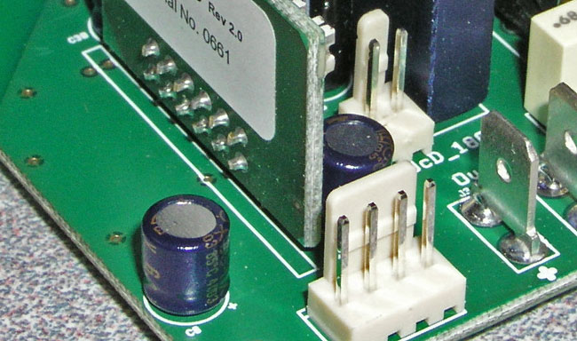
stef1777 said:I've done this on the UcD180 module:
- BB 2134 in place of the original OP
- a KK connector in place of the blue LED (to go to front)
- 47UF BG NX-HiQ for coupling caps
stef1777,
I would like to be able to post nice pictures as well, how did you do it?
Roger
- Status
- This old topic is closed. If you want to reopen this topic, contact a moderator using the "Report Post" button.
- Home
- Amplifiers
- Class D
- Hotrodding the UCD modules