I think you're probably going to have a challenge fitting the drivers and the vents into a box with those required chamber sizes ...
Chamber 1 = 13" x 26" x 7".
Chamber 2 = 13" x 26" x 7".
Chamber 3 = 13" x (width & depth depends on the external folding of Port 2).
Port 1 = 13" x 7" x 0.75".
Port 2 = 13" x 3.5" x 52".
Port 3 = 13" x 14" x 0.75".
In your BP8P, I see you used external ports for Chambers' 1 and 2.
In my BP8S, I need make sure Port 2 feeds into Chamber 1 and Port 1 feeds into Chamber 3.
Manufacturers that have specifications like this are going to have no quality control at all.I am experiencing inconsistencies between the driver manufactures T/S parameters and what I can actually input in Hornresp.
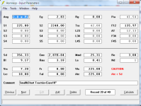
Attachment 1 is a screenshot of the T/S parameters according to the manufacturer (4Ohm driver).
I Double Click on SD, and fill out the "driver parameters" pop up window (attachment 2)
CMS and BL are then automatically calculated but they don't match with BL and CMS figures according to the manufacturer.
Infact BL is 11.64 when it should be 9, and CMS is 1,78E-04 when it should be 2.90E-04.
If I input the BL and CMS figures from the manufacturer's (BL=9 and CMS=0,00029) all the rest of the driver paramaters are automatically updated and no longer match the manufacturer's (attachment3).
In other words, the BL and CMS figures as per the manufacturer's specs do not appear to be compatible with the rest of the driver's parameters.
This issue bothers me because it has a remarkable effect on the power response simulation.
I dont know which of the two simulations should be considered valid, the one where the BL and CMS are automatically calculated or the one after replacing those values with those provided by the manufacturer.
You would be wise to buy, and measure if there is a hoped for cost to performance reason to use these drivers.
I Double Click on SD, and fill out the "driver parameters" pop up window
CMS and BL are then automatically calculated but they don't match with BL and CMS figures according to the manufacturer.
Sd should be 356.33 cm2 not 453 cm2.
Given D = 0.213 m
Diameter = 21.3 cm
Radius = 10.65 cm
Area = Pi * Radius ^ 2
Sd = Pi * 10.65 ^ 2 = 356.33 cm2
For the 4 ohm driver:
Bl spec = 9
Bl calculated from T-S specs = 9.17
Cms spec = 2.9E-04
Cms calculated from T-S specs = 2.87E-04
For the 8 ohm driver:
Bl spec = 12.4
Bl calculated from T-S specs = 12.62
Cms spec = 2.9E-04
Cms calculated from T-S specs = 2.87E-04
I dont know which of the two simulations should be considered valid, the one where the BL and CMS are automatically calculated or the one after replacing those values with those provided by the manufacturer.
Given the closeness of the comparison results I suggest that you simply use the Thiele-Small specifications to automatically calculate the equivalent driver electro-mechanical Bl and Cms values required by Hornresp.
Hornresp Update 5530-240401
Hi Everyone,
BUG FIX
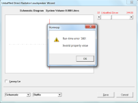
The fatal Run-time error message shown in the attachment was generated if the value of Sd for an unbaffled driver or a driver in a flat open baffle was greater than or equal to 1001, and the S1 slider in the loudspeaker wizard was dragged to the left in an attempt to make the value of S1 less than Sd.
This bug has now been fixed.
Kind regards,
David
Hi Everyone,
BUG FIX
The fatal Run-time error message shown in the attachment was generated if the value of Sd for an unbaffled driver or a driver in a flat open baffle was greater than or equal to 1001, and the S1 slider in the loudspeaker wizard was dragged to the left in an attempt to make the value of S1 less than Sd.
This bug has now been fixed.
Kind regards,
David
Attachments
For the 4 ohm driver:
Bl spec = 9
Bl calculated from T-S specs = 9.17
Cms spec = 2.9E-04
Cms calculated from T-S specs = 2.87E-04
For the 8 ohm driver:
Bl spec = 12.4
Bl calculated from T-S specs = 12.62
Cms spec = 2.9E-04
Cms calculated from T-S specs = 2.87E-04
Further to the above, it would seem that the manufacturer is probably simply calculating the Bl and Cms values from the Thiele-Small values, but is using the generally-accepted approximation of 340 m/s for the speed of sound rather than the Hornresp default setting of 344 m/s.
If so, then this would make the comparison results identical when truncated to one decimal place:
For the 4 ohm driver, assuming c = 340m/s:
Bl spec = 9
Bl calculated from T-S specs = 9.06
Cms spec = 2.9E-04
Cms calculated from T-S specs = 2.94E-04
For the 8 ohm driver, assuming c = 340 m/s:
Bl spec = 12.4
Bl calculated from T-S specs = 12.47
Cms spec = 2.9E-04
Cms calculated from T-S specs = 2.94E-04
Hello @David McBean , I report two bugs
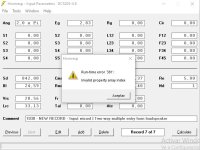
First, creating a new .dat file, click on save, nothing happens and after I click on editor button say error 381 (attachment 1)
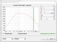
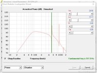
Second, loudspeaker wizard on closed box design, the fudamental frecuency is always the first peak in the graphic (attachment 2 & 3)
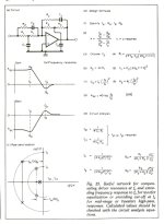
Finally, I have a request if possible add the "Linkwitz Transform" in filter wizard menu (attached 4 of basic formulas and analyses)
Thank you so much.
First, creating a new .dat file, click on save, nothing happens and after I click on editor button say error 381 (attachment 1)
Second, loudspeaker wizard on closed box design, the fudamental frecuency is always the first peak in the graphic (attachment 2 & 3)
Finally, I have a request if possible add the "Linkwitz Transform" in filter wizard menu (attached 4 of basic formulas and analyses)
Thank you so much.
Attachments
creating a new .dat file, click on save, nothing happens and after I click on editor button say error 381
I see what you mean, many thanks for the feedback!
It used to work, so something has definitely gone wrong somewhere. I need to investigate…
loudspeaker wizard on closed box design, the fudamental frecuency is always the first peak in the graphic
Depending upon the loudspeaker design and driver, Hornresp sometimes has difficulty in identifying the fundamental frequency, particularly if the 'resonances not masked' option is being used. Try simulating with the 'resonances masked' option selected instead, to see if this makes any difference.
The impedance chart usually shows the frequency of the actual system resonance quite clearly. Depending upon the design, the displacement chart can also sometimes make it obvious.
I have a request if possible add the "Linkwitz Transform" in filter wizard menu
I know very little about Linkwitz Transform filters. From the information you have provided it would seem that they have the general characteristics of low and high shelf filters, which are already included in the Hornresp Equaliser Filter Wizard.
How many filters would be required?
What would be the slider inputs?
What would be the expressions to calculate gain and phase at a particular frequency, using the slider values as inputs?
I need to investigate…
I have found the problem - it will be fixed in the next update.
Fixed, turning off The Resonances shows the actually fudamental frencuency. I always had it checked for "accurate results".Try simulating with the 'resonances masked' option selected instead, to see if this makes any difference.
In fact, it is the same principle, Linkwitz Transform seeks to extend the frequency response and eliminate peaks to have the response as flat as possible.I know very little about Linkwitz Transform filters. From the information you have provided it would seem that they have the general characteristics of low and high shelf filters, which are already included in the Hornresp Equaliser Filter Wizard.
where:
F0=Fc
Q0=Qtc
Fp=new frequency to extend (ideally new cut-off)
Qp=new Qtc for flat response
The goal is to take F0 and Q0 directly from hornresp and with the sliders choose Fp and Qp and show the value of K which is important to be greater than 0 for the circuit work properly.How many filters would be required?
What would be the slider inputs?
The overall gain of the filter is equation #9, the phase change I'm not sure, but I'm putting some links that have more information about it.What would be the expressions to calculate gain and phase at a particular frequency, using the slider values as inputs?
https://www.linkwitzlab.com/filters.htm#9
https://www.linkwitzlab.com/x-sb80-3wy.htm#part2
Attachments

Thank you David, I did not realize I somehow messed up the excel sheet I use to calculate the various surfaces for rectangular horns, and so SD was wrong.Sd should be 356.33 cm2 not 453 cm2.
Given D = 0.213 m
Diameter = 21.3 cm
Radius = 10.65 cm
Area = Pi * Radius ^ 2
Sd = Pi * 10.65 ^ 2 = 356.33 cm2
For the 4 ohm driver:
Bl spec = 9
Bl calculated from T-S specs = 9.17
Cms spec = 2.9E-04
Cms calculated from T-S specs = 2.87E-04
For the 8 ohm driver:
Bl spec = 12.4
Bl calculated from T-S specs = 12.62
Cms spec = 2.9E-04
Cms calculated from T-S specs = 2.87E-04
Given the closeness of the comparison results I suggest that you simply use the Thiele-Small specifications to automatically calculate the equivalent driver electro-mechanical Bl and Cms values required by Hornresp.
It is a Ciare driver, first time I use a driver of this brand so although a reputable factory I thought that perhaps the TS parameters from the factory might be off.
Thanks for pointing out my mistake (which would probably go unnoticed for the foreseeable future LOL).
@Kravchenko_Audio your remark about the quality of the driver, is it related to the the wrong data I posted ? Or you see something in the TS parameters which is off ?
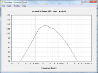
I attach figures and power response, it is a short/small Tractrix midbass horn, 42cm lenght and 70x32cm, intended to cover the range from 100-150 to 600-800 with EQ. Power response is not much different from what I get from a bunch of other drivers, actually some result in more ragged power response. It would be interesting to hear your thoughts on the project after reading your remarks on the driver's TS parameters. Lower range is on a 96db/W/m 18" woofer in a ported 250 liters box.
I have some concerns regarding EBP (152) and BL (9). Also not sure about compression ratio. S1 196 (14x14) CR= 1,8 or 225 (15x15) CR 1.5 don't make much difference in the horn response, so I guess this should be decided on what might work best with the driver.
BTW this is a driver I already own and am willing to accept some compromises.
Attachments
Specifically about the wrong data. If that is how they work, presenting false data that is a not a great company.your remark about the quality of the driver, is it related to the the wrong data I posted ? Or you see something in the TS parameters which is off ?
@Kravchenko_Audio, thanks for your reply.
The data they provided are correct, as confirmed by David McBean.
They appeared to be mistaken due to the mishap with my excel sheet and calculation of SD.
The data they provided are correct, as confirmed by David McBean.
They appeared to be mistaken due to the mishap with my excel sheet and calculation of SD.
The goal is to take F0 and Q0 directly from hornresp and with the sliders choose Fp and Qp and show the value of K which is important to be greater than 0 for the circuit work properly
If all goes according to plan the Linkwitz Transform closed-box bass extension method will be included as an option in the next update.
Interesting read. I guess LTX could be applied to any type enclosure, especially a BP4. If a driver designed to fit in a 1ft3 sealed enclosure, then imagine how a 1ft3 LTX BP4 would perform.
https://www.minidsp.com/applications/advanced-tools/linkwitz-transform
https://www.minidsp.com/applications/advanced-tools/linkwitz-transform
A linkwitz transform is nothing more than just a 2nd order shelving filter with certain parameters.AFAIK Linkwitz transform is specific of closed boxes. How can it be applied to a ported box ? Other than thru Equalization of course...
(= two frequency parameters + two Q-factors)
So technically you can use it for any system you want.
The parameters conversion (as in, the way Linkwitz developed it at that time) only work for closed boxes, but you can just change that manually.
All that being said, ported systems are a lot more receptacle to errors.
A ported system is a (so called) higher order system compared to a closed box system.
The amount of error is always bigger with higher order systems since there are not only more parameters involved but also the interaction between those parameters grows (exponentially if I am not mistaken).
That all sounds very nerdy, but in simple words that means that a ported system is just much harder to keep in line with those simulated/calculated parameters basically.
Or in other words, the reality will most likely not be the same as what you calculated.
")
= system does not sound or behave the way wanted.
@b_force Linkwitz Transform is ideal only for sealed boxes because the characteristics and 12db/oct slope of the LT are good match to the response/behavior of the driver below Fs in sealed boxes.
In ported boxes the behavior is different so I am not sure it makes much sense applying a Linkwitz Transform to a ported box. Certainly the result will be different, and this may defy the very reason to apply a LT instead of some other filter.
Don't you think for this reason it would probably be more effective designing a "custom" shelving filter based on the actual slope of the driver as measured in the ported box ?
REW allows a good flexibility in the creation of LT filters, as well as filters that although not strictly LT are based on same principle (see picture at the link below).
Perhaps now it is more clear why I mentioned Eq. in previous post.
https://www.avnirvana.com/threads/linkwitz-tranform-filter-for-eq-function.9133/
That is basically the same thing as a LT filter, just the name (and parameters) are different.Don't you think for this reason it would probably be more effective designing a "custom" shelving filter based on the actual slope of the driver as measured in the ported box ?
I personally don't think it's very useful to compensate a ported design for the reasons mentioned.
But technically it's an option, can be done and might be useful in some cases.
Stacking a bunch of param EQ can also give the same or a very similar result as a LT btw.
For those who don't have the LT option in their DSP settings.
A linkwitz transform is nothing more than just a 2nd order shelving filter with certain parameters.
(= two frequency parameters + two Q-factors)
HR has more than 2 options in Filter Wizard.
- Home
- Loudspeakers
- Subwoofers
- Hornresp