Reading through that thread there are a couple of comments that have raised questions...
First by Ron E
The driver is always 2 orders, because it is a piston and has a mass. The enclosure in the case of a sealed box just acts to stiffen the spring so it is still second order. An enclosure and port (the port acts like a piston) act as two energy storage components independent of the speaker...
I get that the driver is both a piston and has mass, but I don't see where the mass is coming from in the port to make it 4th order unless you are counting the air weight to get 2 + 2.
The second thing was by 03blueSI
if you add a 4th order crossover (linkwitz/riley) to a 2nd order enclosure you get a 6th order or 36db/octave rolloff.
Is this factually correct?

The chamber parameters in Hornresp (Vrc-Lrc) are for a closed chamber, while in BLH it is an open coupling chamber so I wonder if the simulation of the chamber in hornresp is accurate enough also for a BLH
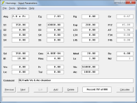
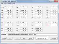
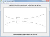
Vtc & Atc would normally be used to specify the chamber in a BLH system, as shown in Attachment 1.
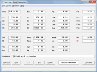
Vrc & Lrc could alternatively be used, but then the design would need to be as shown in Attachment 2.
Attachments 1 and 2 use Driver Position Ratio = 0.0.
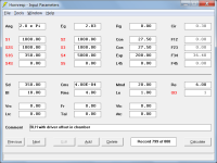
Attachment 3 uses Driver Position Ratio = 0.5.
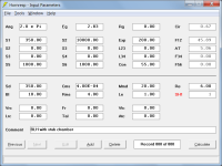
Attachment 4 uses Driver Position Ratio = 1.0.
Attachments
The second thing was by 03blueSI
if you add a 4th order crossover (linkwitz/riley) to a 2nd order enclosure you get a 6th order or 36db/octave rolloff.
Is this factually correct?
Yeah, it doesn't sound right.
Are they referring to a low pass filter or high pass filter? I would think it would have to be a high pass filter to get the steeper roll off.
Was from 2004 so bit late to be asking the poster now. But the general premise seems to be that any electronic filter is added to that natural to the box type.Are they referring to a low pass filter or high pass filter? I would think it would have to be a high pass filter to get the steeper roll off.
Reading through that thread there are a couple of comments that have raised questions...
First by Ron E
The driver is always 2 orders, because it is a piston and has a mass. The enclosure in the case of a sealed box just acts to stiffen the spring so it is still second order. An enclosure and port (the port acts like a piston) act as two energy storage components independent of the speaker...
I get that the driver is both a piston and has mass, but I don't see where the mass is coming from in the port to make it 4th order unless you are counting the air weight to get 2 + 2.
You gonna make me pull out all my old speaker building books!
Yes, it's the air in the port that creates the mass.but I don't see where the mass is coming from in the port
Thank you David that's a very useful feature.Vtc & Atc would normally be used to specify the chamber in a BLH system, as shown in Attachment 1.
Vrc & Lrc could alternatively be used, but then the design would need to be as shown in Attachment 2.
Attachments 1 and 2 use Driver Position Ratio = 0.0.
Attachment 3 uses Driver Position Ratio = 0.5.
Attachment 4 uses Driver Position Ratio = 1.0.
Now taking it one step further...Is it possible to simulate a front loaded horn with a rear chamber which has the same characteristics of the coupling chamber of the BLH ?
In the case of a horn which has both front and rear loading the same chamber serves both the FLH and the BLH.
I can simulate the coupling chamber of the BLH with accuracy in the ways you described in your previous post, and that's ok.
But how do I simulate a "ported" chamber for the FLH (where the "port" is actually S1 of the BLH)?
I guess Vrc and Lrc are normally used to simulate the chamber of a FLH, but those values are related to a sealed chamber, not a ported one.
You gonna make me pull out all my old speaker building books!
D@mn, I USE to keep my audio books in here.
I thought they might be in here from the August 2022 move. That dresser is close to my age! I'll be 55 this year.
Unfortunately, the books are buried in here 🤬
Not strictly hornresp related but since all the horn guys are on this thread...
General consensus is that for some reason horns should ideally be crossed about 1 octave above the horn low cutoff frequency.
Never really asked myself why, so the question is what happens if the electrical filter is centered well below the horn cut off frequency ?
Like a 100/200Hz hi-pass filter on a full range cone driver mated to a 300 or 500hz horn.
Would this be acceptable and what issues one is supposed to face ?
I only build subwoofers and buy CHEAP commercial built PA speakers with horn compression drivers.
I haven't opened up the 8" yet.
The guts use to be on Amazon.com but when I posted my home theater pics, they removed the previous pics.
The 15" fell over and i repaired the left side hole with Gorilla glue.


I haven't opened up the 8" yet.
The guts use to be on Amazon.com but when I posted my home theater pics, they removed the previous pics.
The 15" fell over and i repaired the left side hole with Gorilla glue.
Is it possible to simulate a front loaded horn with a rear chamber which has the same characteristics of the coupling chamber of the BLH ?
Not sure that I understand - if you are asking can the sealed rear chamber on a front loaded horn system act as an acoustic low pass filter, then the answer is no.
In the case of a horn which has both front and rear loading the same chamber serves both the FLH and the BLH.
Once again, not sure that I understand - are you perhaps referring to a compound horn, as shown in Attachments 1 and 2?
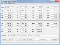
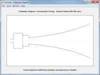
But how do I simulate a "ported" chamber for the FLH
Specify the rear chamber using Vrc & Lrc, and the port tube using Ap & Lpt, as shown in Attachments 3 and 4.
Attachments
@BP1Fanatic so after all that looking did you find the books you were looking for or get yourself sidetracked?
You can also use the CH function to model BP6P's, basically a straight flare compound horn with compression (coupling) chambers. I modeled a couple of CH's in this thread a few years ago and compared them to the BP6 function, Nd segments+Vrc+Lrc+Ap+Lpt, and OD segments+Vrc+Lrc+Ap+Lpt. I think I even used Atc+Ltc as a chamber.Once again, not sure that I understand - are you perhaps referring to a compound horn, as shown in Attachments 1 and 2?
That all brings me back to...if I can model a TL enclosure with the same HR functions as a BR enclosure, then a TL is a BR too.
How is a TL a BR? Just because you can use the same sections of a simulation software to model them?
the length, driver position and sizing info you enter into horn response exposes/manipulates the qw standing waves and their function. It’s not magically the same thing because you use the same section of the software?
the length, driver position and sizing info you enter into horn response exposes/manipulates the qw standing waves and their function. It’s not magically the same thing because you use the same section of the software?
Last edited:
- Home
- Loudspeakers
- Subwoofers
- Hornresp