So two dual voice coil subwoofers wired to Paralel-Series resulting 0.7ohm load on amplifier. How can I simulate this in hornresp?
If the two voice-coils are connected in series then set Re = 0.7 + 0.7 = 1.4 ohms and specify BP6 = 2P for two drivers in parallel.
Attachments
Based on your answer I assume that the format must be precisely equals to what hornresp export do.
If you want to export a data file from your CAD software that Hornresp can recognise and import, then the easiest way to do it would be to use the existing BOXPLAN format, as shown in the attachment.
It would be very welcome if you could test it.
There's really no need for me to test it - you can easily do that for yourself
") .
.Attachments
If the two voice-coils are connected in series then set Re = 0.7 + 0.7 = 1.4 ohms and specify BP6 = 2P for two drivers in parallel.
Alternatively, if the two voice-coils are connected in parallel then set Re = 0.35 ohms and specify BP6 = 2S for two drivers in series.
If the two voice-coils are connected in series then set Re = 0.7 + 0.7 = 1.4 ohms and specify BP6 = 2P for two drivers in parallel.
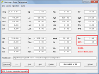
Okay I get it, but what about wattage simulation? If I want to simulate 5000w per subwoofer (10000w total for two) and if final load is 0.7ohm, what should I type in this form?Alternatively, if the two voice-coils are connected in parallel then set Re = 0.35 ohms and specify BP6 = 2S for two drivers in series.
I found this image in one hornresp manual.. If this is right then in my case lc2 would be 135cm and lc1 79cm right?The driver offset is zero. Because of the nature of the enclosure layout is difficult to specify Lc1 and Lc2 as exact accurate lengths. Thankfully it doesn't matter too much - try changing the Lc1 and Lc2 values to see how the response alters. If you click on the Lc1 and Lc2 sliders, the red line that appears on the system model acoustic circuit diagram shows what the simulation model is assuming are the lengths.
Hi,
i know wine is not supported, anyway i observed the following about the ripole settings:
When i create a ripole with the input-wizard, i get after the wizard: ERROR isobaric driver.
When i then double-click on "OD"(which shows 2p, lower case p) and choose "Drivers in parallel = 2",
OD then shows "2P"(upper case P) and the error changes to: Note, Ripole folded baffle.
I then can happily simulate the ripole.
Is it then simulated for one or two drivers? I mean, is the 2P setting in a ripole the setting for one driver emitting
to front and rear? It also seems it makes no difference for the frequency response when i set OD to 2S.
No, no. I was talking about just the help window being larger and with a bigger font. The app itself is fine as is. You have provided a decent help system but that also means there's a lot of material to go through.It wouldn't help, see Attachment 1.
It wouldn't help, see Attachment 2.
Hornresp currently has forty six forms and several hundred control objects on those forms. Each form and control object would need to have its Left, Top, Width, Height and Font Size property values changed. The schematic diagram, system model and chart graphics would also all have to be re-scaled. The task would be absolutely massive. It's not going to happen.
I often open the help file in multiple windows so that I can read a different section in another window without losing my place in the first window. Index and navigation buttons would be great, but are not critical - your time is better spent on developing the main program. 👏
@SamAnytime in help, click on File>Export and it is saved as a text file.
Thank you, Boxplan is a simpler format, I already implemented a full export as hornresp, but following boxplan format will save some time.existing BOXPLAN format, as shown in the attachment
There's really no need for me to test it
It's just as curiosity, to see how cad can integrate with Hornresp, and it could be a good test for me, mainly if you don't know how to use CAD. Easier I make it, better it can be if other wants to use it. I may open an threat to see if there is interest on it. Maybe it'd fun only for me, we never know.
... or just right click the file Hornresp.hlp and Open with Notepad etc. (we do lose the clickable content list though).@SamAnytime in help, click on File>Export and it is saved as a text file.
what should I type in this form?
The load seen by the amplifier, and the power that the amplifier needs to deliver to the load.
That is:
Power in watts = 10000
Load impedance in ohms = 0.7
If the impedance of each driver reduces to exactly 1.4 ohms at some very low frequency (it would have to be close to f = 0), then the input power to each driver at that frequency will be 5000 W, and the total power delivered by the amplifier will be 10000 W.
In practice, the impedance is unlikely to get down to to 0.7 ohms so that the actual maximum input powers will be somewhat less that the figures shown above.
I found this image in one hornresp manual.. If this is right then in my case lc2 would be 135cm and lc1 79cm right?
No image included.
The System Model shows that:
Lc1 is the acoustic path length from one side of the driver diaphragm, through Chamber 1 to the input of the port tube that vents externally.
Lc2 is the acoustic path length from the other side of the driver diaphragm, through Chamber 2 to the input of the port tube connecting Chamber 2 to Chamber 1.
Based on the diagram and dimensions given:
Lc1 is likely to be somewhere near 135 cm
Lc2 is likely to be somewhere near 79 cm
Try using these values initially, and then adjust them to see how sensitive the results are to any changes.
When i create a ripole with the input-wizard, i get after the wizard: ERROR isobaric driver.
The Input Wizard output is normally 2P not 2p.
It seems that Wine is having trouble recognising the difference between upper case P and lower case p.
Is it then simulated for one or two drivers?
Two drivers are being simulated, as in a standard ripole system.
It also seems it makes no difference for the frequency response when i set OD to 2S.
When the two drivers are connected in series rather than parallel, the power response output is reduced by 20 * Log(2) or 6.0206 dB.
In the case of the Input Wizard generated example, for a parallel connection the level at 100 Hz is 82.7893 dB and for a series connection it is 76.7687 dB, the difference being exactly 6.0206 dB.
Last edited:
It's just as curiosity, to see how cad can integrate with Hornresp, and it could be a good test for me, mainly if you don't know how to use CAD.
I did not realise that you were suggesting that I test the CAD package itself.
I just thought that you wanted me to test that the exported CAD records worked okay in Hornresp
.Two drivers are being simulated, as in a standard ripole system.
At the moment it is not possible to specify a single-driver ripole system. Is anyone likely to want to simulate one?
I'd like toAt the moment it is not possible to specify a single-driver ripole system. Is anyone likely to want to simulate one?
From https://www.lautsprechershop.de/hifi/aka_sub_sonder_en.htm ,
the current Hornresp Ripole is the W-Profile(BMC-Ripole, two drivers) ,
and there is also the N-Profile(RDS-Ripole, one driver), both by Mr. Ridtahler.
It might also be useful to be able to simulate a expanding/tapered Ripole to move the resonant peak, like in this picture:

Also thank's for the ripole clarifications above!
Last edited:
Hi rertrobaer,
Thanks for the feedback and the link.
The next release will enable a single-driver Ripole system to be specified.
Including the expanding / tapered option would require a complete change to the way that a Ripole is specified in Hornresp. I will have a look, but I cannot promise anything at this stage.
Kind regards,
David
Awesome, thanks very much!The next release will enable a single-driver Ripole system to be specified.
Maybe it's not worth it, i don't know. I did try what impact it would have, the max resonance peak shift up in a 30cm long Ripole was from about 250Hz(straight ripole) to 320Hz(expanding S1=300,S2=30).Including the expanding / tapered option would require a complete change to the way that a Ripole is specified in Hornresp. I will have a look, but I cannot promise anything at this stage.
Another thing about dipole/Ripole: Maybe it would help to be able to set the distance of a rear wall behind the enclosure as source of the rear-mouth
via "Path" in Power/Chamber/Combined.
I think this this would come more close to reality for the "Power/(Ripole-,U-Frame,H-Frame) Baffle/Combined" frequency response, as it would take the reflection from the rear wall into account.
The cancelation on the low end seen in "combined" caused by the 180° phase shift from the rear doesn't happen to that extend in reality with open baffles.
I did not realise that you were suggesting that I test the CAD package itself.
Hello David,
I would appreciate a lot if you cold spent some minutes testing it.
Here you get some information and the files.
https://www.diyaudio.com/community/...c-cad-and-hornresp-volunteers-request.390852/
- Home
- Loudspeakers
- Subwoofers
- Hornresp