Richard Heyser wrote that group delay is only an accurate description of the actual time delay through the system for the non-minimum-phase part of the response. He had some math to back it up.
As for low frequency time distortion, Lara Harris and Keith Holland have done some interesting work: https://eprints.soton.ac.uk/426110/1/RS2018_HarrisEtAl_Final.pdf
As for low frequency time distortion, Lara Harris and Keith Holland have done some interesting work: https://eprints.soton.ac.uk/426110/1/RS2018_HarrisEtAl_Final.pdf
As for low frequency time distortion, Lara Harris and Keith Holland have done some interesting work: https://eprints.soton.ac.uk/426110/1/RS2018_HarrisEtAl_Final.pdf
From that paper - ", frequency-dependent phase shifts, such as those accompanying resonances and rapid roll-offs in a loudspeaker alignment, change the relative delay between individual components in a signal, rather than delaying it as a whole. This effect, commonly known as group delay, is also referred to as envelope delay [snip], where the shape, or envelope, of a
signal in the time domain is changed such that the acoustic output is not simply an amplitude-scaled version of that presented at its input terminals. "
That seems to be one of the better descriptions that I've seen of group delay.
could that not be looked at as hysteresis?
You mean group delay? I can't see how. Hysteresis is a nonlinear phenomenon, group delay exists also in linear systems. Depending on the system, they may be loosely related somehow, but not in a way that would make it possible to describe one in terms of the other.
Um, front loaded horns are basically bandpass enclosures
Badly-designed bandpass enclosures tend to have high out of band resonance peaks, which might be what you're hearing. And tapped horns are basically bandpass enclosures with high out of band resonance peaks, so....
Tell me you are yanking my chain!
a bandpass has two humps. ( Bactiran enclosure ) And the interior of the humps is filled in mostly by harmonics generated in the system.
Please explain to me where in the useful passband you rely on harmonics in a well designed front loaded horn?

@ Bjorn
Thanks for the link. It will be interesting to read.
+1, was a good read
Tell me you are yanking my chain!
a bandpass has two humps. ( Bactiran enclosure ) And the interior of the humps is filled in mostly by harmonics generated in the system.
See attached - is that the impedance curve of a bandpass subwoofer or a front-loaded horn? Looks like two big humps to me
And the interior of the humps is filled in mostly by harmonics generated in the system.
That makes no sense to me. With my bandpass builds, I put 50 Hz in, I get 50 Hz out. Very little harmonics, and what there is in harmonics is distortion, not something generated by the design itself. Actually good bandpass systems are characterized by having LESS HD than equivalent direct systems like sealed and vented using the same driver - a positive feature of the acoustic filter.
Attachments
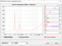
I understand your two bumps. That's impedance. Not the same thing as I am talking about.
I'm referring to the frequency response.
And yes that the resonant systems are filling in the middle with harmonics is a well known attribute of a bandpass system. I first read about that in the late 80's Mark Gander and Earl Geddes when they were both working for Ford.
Your 50 hertz in 50 hertz out is interesting. But I have to ask, What is the tuning ratio between the upper and lower tuning on that particular box? If it is near 50 hertz you are getting as clean as it is possible out of that enclosure.
I did an experiment quite a few years ago using the same driver sin 4 different enclosure type. Front load to vented with a resonant system being one of them. I could readily hear the distortion in that test situation. ANd back when I was doing a lot of enclosures for customers I was building bandpass boxes and again. Heard the distortion readily. Back then I didn't have much test gear. 30 years ago I mean.
Your ability to discern distortion depends on the program material. I'm positive that you know this Brian.
Same goes for the pleasing effects to many of the increase in low frequency distortion. It sounds louder, fuller. But it isn't as accurate to the incoming signal.
Last edited:
I've actually built and measured some bandpass systems as well.
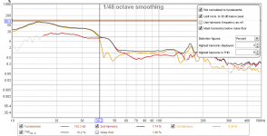
They feature LESS distortion than direct systems like sealed or vented. Because of the acoustic bandpass. Here's one example, driven at its PEAK design voltage. Notice the THD throughout its passband and down to the end of its design passband (40 Hz). Notice that it only starts rising below 50 Hz? That's a direct result of the system's upper passband limit of just over 100 Hz. Any signal above 50 Hz is going to have harmonics above 100 Hz, and they will all be reduced by the acoustic filter's effective LP at just above 100 Hz.
The "gap being filled in by harmonics" simply makes no sense at all.
I don't know what you were hearing, but if it was a well-designed bandpass system, I'm pretty sure that it was not distortion. At least not harmonic distortion. Again, more likely it was the out of band resonances. If you were doing this 30 years ago, the tools available at the time would likely have been lumped-mass modeling tools that could not model those resonances, and therefore there was no easy way for adjusting the design to minimize them.
Attachments
Last edited:
I've actually built and measured some bandpass systems as well.
They feature LESS distortion than direct systems like sealed or vented. Because of the acoustic bandpass. Here's one example, driven at its PEAK design voltage. Notice the THD throughout its passband and down to the end of its design passband (40 Hz). Notice that it only starts rising below 50 Hz? That's a direct result of the system's upper passband limit of just over 100 Hz. Any signal above 50 Hz is going to have harmonics above 100 Hz, and they will all be reduced by the acoustic filter's effective LP at just above 100 Hz.
The "gap being filled in by harmonics" simply makes no sense at all.
I don't know what you were hearing, but if it was a well-designed bandpass system, I'm pretty sure that it was not distortion. At least not harmonic distortion. Again, more likely it was the out of band resonances. If you were doing this 30 years ago, the tools available at the time would likely have been lumped-mass modeling tools that could not model those resonances, and therefore there was no easy way for adjusting the design to minimize them.
What??
Your interest in paraflex lately needs to expand into a real device to listen to and test. In fact an offset driver version with a rear chamber and offset geometry of its own( a mini mirror if you will) in the same basic format and/ or pressure and phase result is the aactual paraflex model to consider here. It has results. They are not in question. They exist the moment you build it. And while thats not ever going to be ‘perfect’, its close enough to notice something is definitely not the same. And one look at the solar system is ironic enough for me.
Sun is 0.0pi, merc 0.4, veus 0.71 and earth 1.0.
Mars is 1.6.
Jupiter 5.236. pi/6(?) x10x^xxxx
Saturn is 10pi.
Now reduce that by orbital and planet individual diameters and speeds and you get sinewave nodes and pressure antinodes found in the maths of pythago.
Offset driver and 0.349.
360 degrees on 3.1416 is 1130.
And the rest is very very strange but real.
Put pipe physics into the pipes. Use harmonics as a guide
That gap does whatever it does..
In our solar system its a torrid meteor shower twice a year (and much much more in due time!!)!. Weather or not thats got anything to do with anything is beyond me... but im not a profesional speaker person, or an astrophysist. Im just having accidental fun with landmark realities
pi/6 in (30 dehrees)) to the 90 degrees mismatched in a ‘TL/ pipe, is taking the 90 degrees out of the qw pipe in every rotation in every step to infinity. Harmonics are helping not hindering. Line them up using horn response
Last edited:
The attachments show the predicted group delay results for a representative 14 Hz exponential horn of length 8 metres. At 20KHz the signal delay is almost entirely due to the time it takes for the sound to travel through the horn. At high frequencies the delay through the drive unit itself is relatively small.
At 20KHz:
Predicted signal delay = 23.3426 milliseconds
Horn length = 8 metres
Velocity of sound = 344 metres per second
Delay through horn = 8 / 344 * 1000 = 23.2558 milliseconds
Delay through driver = 23.3426 - 23.2558 = 0.0868 milliseconds
It is interesting to note that at 10Hz the signal through the system is delayed by 18.7659 milliseconds, meaning that for the chosen example at least, at that frequency the delay through the driver has a negative value of 18.7659 - 23.2558 = -4.4899 milliseconds.
4.4899 milliseconds difference within the passband 10hz to 20khz.... Thats not a group delay problem, thats tighter grouping than sealed cabinets even (highly desireable) ...too bad something like this could not be used with live video....I bet teh phase goes crazy up top as well...would have to use linear filter to cross it over if that was the goal...al the bass horns I've designed (in HR) have that trait in phase at least
Richard Heyser wrote that group delay is only an accurate description of the actual time delay through the system for the non-minimum-phase part of the response. He had some math to back it up.
As for low frequency time distortion, Lara Harris and Keith Holland have done some interesting work: https://eprints.soton.ac.uk/426110/1/RS2018_HarrisEtAl_Final.pdf
Finally a respectable name on the group delay train....maybe I'll earn some credibility now.
Despite this, the industry standard still
prioritises representations of the extension and flatness of the frequency response magnitude over
transient accuracy, even for loudspeakers intended for professional use
Not my mastering monitors =)
Last edited:
Richard Heyser wrote that group delay is only an accurate description of the actual time delay through the system for the non-minimum-phase part of the response. He had some math to back it up.
https://www.aes.org/technical/documents/openaccess/AES_TimeDelaySpectrometry.pdf
I can hear it...its not something the average person can pick out...it needs to be rather high in the region where I hear it and must be able to a/b material between the system in question and headphones... it becomes a critical issue for me in the tuning of compression on bass...it makes the bass sound as if it has a compressor on it with a quick release....it also affects perception of the attack envelope in particular an issue with tweaking the attack envelope of a compressor or electric bass instruments.... as a musician and sound engineer I am sensitive to time based distortion....but I have only claimed to hear it in bass...a my current subs are vented with no dampening material which is a classic case for high group delay around tuning. It sounds as a late arrival of lower bass signal in my system...I can pick it out of the play back of various bass drums.
A front loaded horn tuned to 14hz doesn't have group delay issues lol...not to mention that the lower the note the higher group delay has to be for its perception...tuned to 14hz group delay of your horn was like that of a sealed above tuning....that is in comparison to the rest of the spectrum vs tuning where group delay peaks
We need to play some legit material through some intentionally ‘altered’ speaker pipes with this. Ie: the PH sim with phase aligned out to well
Above the passband and not the typical qw pipe 3 x Fb issue, or the briefly smeared version in of typical OD TL.. step it up. Get into the next level of Fournier! Pipes fix pipes. Pipe lives matter LOL
Hey guys, I have a problem with the slidebars in Hornresp.
From one day to another, I am not able to use them anymore, in any kind of situation (to select multible drivers, apply an EQ or filter, most dramatic is that I cant use the loudspeaker wizard anymore :/)
I don´t think it´s a problem with Hornresp itself, as it appears in all different versions, those I have on my pc since a year, and the newest downloaded...
Anyone knows this bug and how to solve it?
Last edited by a moderator:
- Home
- Loudspeakers
- Subwoofers
- Hornresp