Maybe ‘helpful’ in the troubleshooting? OD, with ‘closed’ mouth. Click on ‘QL’ on main screen or try to go into ‘wizard’ in tools and its likely to get this(pic)?
Note: I am possibly creating an issue as i have multiples of it open for comparing drivers (not sure if thats a factor but important to mention i think)?
Note: I am possibly creating an issue as i have multiples of it open for comparing drivers (not sure if thats a factor but important to mention i think)?
Attachments
Last edited:
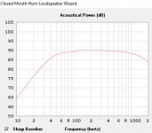
Remember that Hornresp is showing you the power response, not the on-axis response....SPL did rise a bit above 1kHz, but still rolling off dramatically compared with the manufacturer's freq response. Still wondering...
Think of it as what you would measure with an RTA compiling an average response as you walk all the way around the speaker enclosure.
Remember that Hornresp is showing you the power response, not the on-axis response.
Think of it as what you would measure with an RTA compiling an average response as you walk all the way around the speaker enclosure.
Thanks!
I have been thinking about directivity a bit, but I'm admittedly new to this. The design has a rear-firing BLH that'll fire toward a wall, tuned to 80Hz - 400Hz, and now a small FLH tuned down to 250Hz to counter the strong bass from the BLH. The coupling chamber for the BLH could be tuned as high as 600Hz, but I thought it'd be better not to have too high a ceiling because of directivity.
I haven't completed playing around with that crossover between the two sources, but is the way of thinking about it on track?
I am possibly creating an issue as i have multiples of it open for comparing drivers
Hornresp was never designed to handle multiple simultaneous sessions. Installing and running multiple copies of the program can in the worst case lead to a complete loss of all permanently stored design records. The error you have experienced is a mild outcome compared to what can possibly happen, depending upon the circumstances.
I strongly recommend that you immediately delete all but one of your Hornresp installations.
Note - you have been warned. Don't blame me if you keep running multiple copies, and then one day all your valuable stored data suddenly disappears...
") .
.Hornresp was never designed to handle multiple simultaneous sessions. Installing and running multiple copies of the program can in the worst case lead to a complete loss of all permanently stored design records. The error you have experienced is a mild outcome compared to what can possibly happen, depending upon the circumstances.
I strongly recommend that you immediately delete all but one of your Hornresp installations.
Note - you have been warned. Don't blame me if you keep running multiple copies, and then one day all your valuable stored data suddenly disappears...
Oh!! good thing i asked, thank you for the heads up David
Hornresp was never designed to handle multiple simultaneous sessions.
Just in case you're interested, there's actually a way to block this from happening using Visual Basic coding.
This is how I do it in one of the applications I've coded.
'Check to see if another copy of the application is running
If Process.GetProcessesByName(Process.GetCurrentProcess.ProcessName).Length > 1 Then GoTo ExitMain
"ExitMain" is a separate routine in the application that I put together to ensure that the application ends cleanly.
So, by adjusting the radiation angle, one should be able to emulate the on-axis response of a direct radiator?
To calculate the on-axis pressure response of a direct radiator loudspeaker, select the menu commands Tools > Directivity > Response from the main Acoustical Power chart window.
This is how I do it in one of the applications I've coded.
Hi Brian,
I currently use the statement:
If App.PrevInstance = True Then End
to prevent multiple copies of the same Hornresp.exe file from being opened.
This however does not prevent:
1. Multiple copies of Hornresp.exe stored in different folders from being opened.
2. Multiple copies of Hornresp.exe with names changed stored in the same folder from being opened (eg. Hornresp.exe, Hornresp1.exe, Hornresp2.exe).
Technique 1 has the disadvantage that each copy of Hornresp has its own data file, so that changes made using one copy of Hornresp are not seen by the other copies.
Technique 2 has the advantage that a single common data file is used, but it is possible under some conditions to corrupt the file and lose everything, as previously mentioned.
I am not familiar with the "GetProcesses" code you show (you would be surprised at how little I really know about Visual Basic) but could it handle multiple copies of Hornresp with different file names anyway? Technique 2 is the one most likely to be used by people because the same records can be shared across different open copies of Hornresp (but as indicated above the technique comes with significant risks).
Kind regards,
David
Last edited:
You could address situation #2 by have Hornresp check its name on starting
Now that's an idea - thanks!
Modifying my existing statement as follows, should do the trick nicely:
If App.PrevInstance = True Or App.EXEName <> "Hornresp" Then End
As far as technique #1 is concerned, data loss is unlikely because of the separate data files, and the technique is not likely to be used much anyway, because of the difficulty in maintaining the same data in each instance of the program.
Last edited:
Stupid question: Is this, uh,...good?
I've been tweaking my model like a madman to achieve as flat a response curve as I can across the broadest spectrum of F that I can. Being new to this, it's hard to tell when to stop. That is, to know whether these results are at a stage where I can stop modeling, update the physical cabinet design and start building.
Here's some background: This is modeled with an FR Dayton Audio PS180-8, 6.5" driver. The design is a compound horn, with the BLH rear-firing toward a nearby wall. The FLH was needed to fix the response curve sloping downward from 80Hz - 1kHz. I'll make the front horn and the rear chamber on the lathe. The rear chamber's volume is quite small, such that the smallest driver-enclosing rectangle/depth would force it to be too big and short, so it'll be a true cylinder.
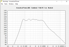
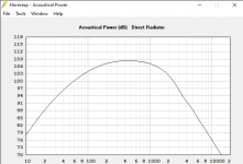
I know from a recent RTFM moment from David McB (I did deserve that), that an FR driver represented in Hornresp will be depicted as rolling off at higher frequencies. In addition to the F response chart for the design, I also attached the infinite baffle F response curve here, because it seems to me that, if conservation of energy applies, the area under the curves must be the same, and if true, I have pretty close to the flattest, broadest response curve I could possibly get--all the wiggling is within 118-121dB. But that is the fundamental question.
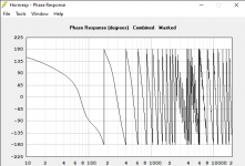
In addition, I'm not sure I have good phase response or directivity, given two horns firing in different directions. For the length of the acoustic path between point sources, I used the distance from the front radiator to the middle of the BLH mouth in my tentative design, about 81cm, but maybe that should measured back to the wall?
Feedback/advice much appreciated!
I've been tweaking my model like a madman to achieve as flat a response curve as I can across the broadest spectrum of F that I can. Being new to this, it's hard to tell when to stop
. That is, to know whether these results are at a stage where I can stop modeling, update the physical cabinet design and start building.Here's some background: This is modeled with an FR Dayton Audio PS180-8, 6.5" driver. The design is a compound horn, with the BLH rear-firing toward a nearby wall. The FLH was needed to fix the response curve sloping downward from 80Hz - 1kHz. I'll make the front horn and the rear chamber on the lathe. The rear chamber's volume is quite small, such that the smallest driver-enclosing rectangle/depth would force it to be too big and short, so it'll be a true cylinder.
I know from a recent RTFM moment from David McB (I did deserve that), that an FR driver represented in Hornresp will be depicted as rolling off at higher frequencies. In addition to the F response chart for the design, I also attached the infinite baffle F response curve here, because it seems to me that, if conservation of energy applies, the area under the curves must be the same, and if true, I have pretty close to the flattest, broadest response curve I could possibly get--all the wiggling is within 118-121dB. But that is the fundamental question.
In addition, I'm not sure I have good phase response or directivity, given two horns firing in different directions. For the length of the acoustic path between point sources, I used the distance from the front radiator to the middle of the BLH mouth in my tentative design, about 81cm, but maybe that should measured back to the wall?
Feedback/advice much appreciated!
Attachments
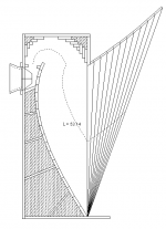
Newracer - do you have drawings / sketches of your design?
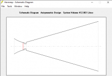
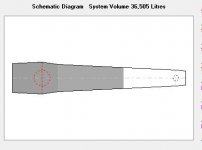
Not exactly, Neil, but attached is something close--the out-of-date design. I've been making so many modeling changes, I decided to stop trying to keep up with the physical design until I could converge on a good schematic. The attached is the side view of the basic format though. Key differences:
- The BLH won't have an offset driver.
- The FLH has a small rear chamber
- And the BLH will expand linearly (conical), not exponentially.
I'll likely have to fold the horn differently, though, with the driver nearer the top of the cabinet.
Hope this helps--LMK.
Attachments
Mixing different drivers and "save" from Loudspeaker wizard, and answer Yes when it ask me if i want to save the records when starting a new design. Despite that nothing is saved.
Are you running multiple copies of Hornresp, by any chance?
By using multiple modes of Horn Response on the same driver, in a variety of sims from qw pipe to offset qw pipe, just slightly tapped qw pipe to the location far inside the pipe. i didnt realize i could screw up my deal, but often it wasnt simultaneously... often it was two computers or two seperate times on it.
This lead me to believe that if the fold was included in horn response then a 1/4,2/4,3/4 pipe with a driver (also at 3/4 via ‘tapped’ ) that was 4/4 of a qw previously, was now able to be much much more than suggested by horn response. Since i refused to start all over and try to stretch that into akabak i just confuse people with my attempts to explain what was possible missing in the idea of a folded version of what i just explained, or similar. If an answer was t so ‘careful’ and caring about what i might screw up, could the answer be the backwave or the offset driver at 1/3 is now seen as 3/4 of 4/4 as in tapped at 3/4? But not shown as such in the unfolded sim? Assuming the fold is at the 2/4 mark. What is missing that im sort of seeing in offset chamber versions?
Or feeling like i could see it if i could ‘add’ another detail? A fold at the middle of a line split by the drivers taps has some ideas of its own merit as well? Its a fold at 1/2 on each side of the middle.. middle being the tapped entry of a twice as long ‘ qwqw pipe ‘...??
I think horn response is suggesting something to me. But if im right i cant tell, i can only wish it could talk to me
Last edited:
I've been tweaking my model like a madman to achieve as flat a response curve as I can across the broadest spectrum of F that I can. Being new to this, it's hard to tell when to stop
Here's some background: This is modeled with an FR Dayton Audio PS180-8, 6.5" driver. The design is a compound horn, with the BLH rear-firing toward a nearby wall. The FLH was needed to fix the response curve sloping downward from 80Hz - 1kHz. I'll make the front horn and the rear chamber on the lathe. The rear chamber's volume is quite small, such that the smallest driver-enclosing rectangle/depth would force it to be too big and short, so it'll be a true cylinder.
I know from a recent RTFM moment from David McB (I did deserve that), that an FR driver represented in Hornresp will be depicted as rolling off at higher frequencies. In addition to the F response chart for the design, I also attached the infinite baffle F response curve here, because it seems to me that, if conservation of energy applies, the area under the curves must be the same, and if true, I have pretty close to the flattest, broadest response curve I could possibly get--all the wiggling is within 118-121dB. But that is the fundamental question.
In addition, I'm not sure I have good phase response or directivity, given two horns firing in different directions. For the length of the acoustic path between point sources, I used the distance from the front radiator to the middle of the BLH mouth in my tentative design, about 81cm, but maybe that should measured back to the wall?
Feedback/advice much appreciated!
How much power are you hoping to pour into this little woofer?
It only has a 25mm or 1 inch voice coil. And the wire gauge will be nearly tweeter thickness to keep up the motor force. 30 watt peaks for a brief time only. Remember that even at the very wishful efficiency rating this driver is almost 95% inefficient. Which means almost all the power going into the driver will get turned into heat!
Other wise.
You have a really flat back loaded horn. But huge!
Are you hoping that the rear wall and or corner will augment what you have worked out?
I do that sometimes, but only to be able to do a quick side by side comparison of the effects of some change in design. Hornresp supports comparison of the current design and the one just before that, but sometimes you have to make several changes to get everything working just right, and by then you lose the comparison with the original design. So if I have an idea I want to try, I make a copy of the entire Hornresp folder and run the second instance from there, and then I can keep referring to my original design. In most cases my new idea is a flop, and then I simply delete the copied folder. If it works, I create a new record in the main Hornresp folder and manually enter the new parameters there, and then I delete the copied folder.As far as technique #1 is concerned, data loss is unlikely because of the separate data files, and the technique is not likely to be used much anyway, because of the difficulty in maintaining the same data in each instance of the program.
I'm glad Hornresp allows me to do that. With some other software (not speaker related) I can only run one instance at a time, and then I've had to run the other instance in a virtual machine or even on another computer.
I have had this happen a fair bit - but not all the time. It feels like a bug?
I actually got it solved. Reinstalled the program (cared to save all the data before, which wasn´t necessary).
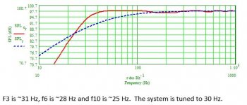
I have a design for SB17NRX2C35-8 done by Paul Kittinger (Google if you don´t recognize the name, who has won a ton of prices for his designs) based on MathCAD by Martin King.
The design is a combination of things I and him have found good in past designs. TSML-TL = Tapered stepped mass loadedd transmission line. The design has an interstingly low f3 and nice smooth spl curve despite rather small volume <37 litres.
Two things:
1)
I have two graphs on the same design - but quite different. One from MathCAD (with little higher input, so don´t care about the showed different output levels) and one from Hornresp. As Hornresp doesnt handle the stepped design into a tapered line I have had to adapt to Hornresp. QUESTION: Are there any other ways to adapt (as my begging to David about this missing feature hadn´r turned out so well until now ) to simulate the step between L23 and L34?
2)
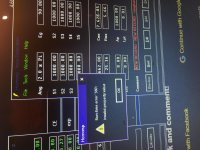
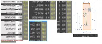
OFFERING: I am a lot better with excel than other things. I very often do my designs from a sketch which then input to a modelling Excel sheet for that specific type of design. It makes it very easy to get all the different specs for volumes angles etc right. Take a look at the Excel sheet picture below and you will understand. I like this kind of nerd work so - If anyone is interested I have this and some other designs that you can utilize from. And maybe set up some new ones. It´s also possible to make board saw designs. Just come back to me.
The design is a combination of things I and him have found good in past designs. TSML-TL = Tapered stepped mass loadedd transmission line. The design has an interstingly low f3 and nice smooth spl curve despite rather small volume <37 litres.
Two things:
1)
I have two graphs on the same design - but quite different. One from MathCAD (with little higher input, so don´t care about the showed different output levels) and one from Hornresp. As Hornresp doesnt handle the stepped design into a tapered line I have had to adapt to Hornresp. QUESTION: Are there any other ways to adapt (as my begging to David about this missing feature hadn´r turned out so well until now
) to simulate the step between L23 and L34?2)
OFFERING: I am a lot better with excel than other things. I very often do my designs from a sketch which then input to a modelling Excel sheet for that specific type of design. It makes it very easy to get all the different specs for volumes angles etc right. Take a look at the Excel sheet picture below and you will understand. I like this kind of nerd work so - If anyone is interested I have this and some other designs that you can utilize from. And maybe set up some new ones. It´s also possible to make board saw designs. Just come back to me.
Attachments
- Home
- Loudspeakers
- Subwoofers
- Hornresp