
Can you add an option to simulate also the aspect ratio of the port?
I don't now if it is possible or how much is difficult to do it
All the Hornresp models assume axisymmetric segments / chambers / port tubes - the predictions are usually close enough for practical purposes. Moving from a circular to a rectangular cross-section would required completely different and significantly more complex simulation models, not to mention the need for a totally new set of input parameters to specify the rectangular cross-sections.
In other words, it's not going to happen
.Not sure about 400Hz since the vent likely won’t have much output,
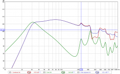
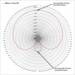
Attached is the predicted output from the vent of an MLTL that I designed using Hornresp (build here: The Subwoofer DIY Page v1.1 - Projects : The Boom Unit), There's a peak just above 300 Hz that's only 6dB below the vent's peak output, and about 1dB down from the driver's response at that frequency. From 226 Hz up, Hornresp is predicting that the vent output is going to have a noticeable impact on the overall response of the MLTL, with a big null centered around 400 Hz.
but if you are making measurements near the enclosure where distances (mic-to-vent) and (mic-to-woofer) have significant differences you will see differences in summation as you move around the enclosure. But, at low frequencies you will find that the power response is a better match for what you would measure in an outside ground-plane test at a typical listening distance of a couple meters.
Actually I expect the impact at 400 Hz to be more noticeable as the length of the "arc" that the nulling effect will be noticeable will widen. But one could argue that 400 Hz isn't really that "low"
There are however examples of the low frequency outputs of two sources deliberately set a specific distance from each other to reduce output levels in one direction while increasing it in the other. End-fire subwoofer arrays for example. And the effect isn't only noticeable when the listening position is close to the subwoofers. For example, if I designed this particular MLTL so that its vent was 1/2W @ 50 Hz separated from the driver and laid it facing upwards like in my previous illustration, the response at bass frequencies will differ significantly, depending on whether or not I took the measurements in front of or behind the speaker. But from what you're saying, Hornresp will indicate that the frequency response should be the same at both locations.
Attachments
Questions, is it possible to model the influence of the port aspect ratio in the simulations?
We had a discussion about this a few years ago. See:
Hornresp
Hornresp
Hornresp
Essentially you correct the port length used in the simulation manually by the difference in length correction between a round and a rectangular port.
We had a discussion about this a few years ago. Essentially you correct the port length used in the simulation manually by the difference in length correction between a round and a rectangular port.
Hi Bjørn,
Your memory is much better than mine, it would seem
.What about at the outlet end of the port tube, where Hornresp uses the radiation impedance of a circular piston, rather than a "mass" virtual length correction? I was assuming that it would be necessary to calculate the radiation impedance of a rectangular piston, a complication I can definitely live without
.Kind regards,
David
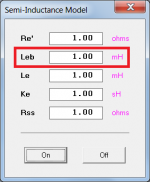
If "semi-inductance" is enabled, adjusting the driver's Le in the Loudspeaker Wizard makes no difference to the response curve.
That's because the semi-inductance model replaces Le and Re.
I typically do that at times to see what impact the inclusion of a series inductor might have on the system's response.
Increase the value of Leb to include a series inductor. This can only be done on the main input window though - not in the wizard.
Attachments
What about at the outlet end of the port tube, where Hornresp uses the radiation impedance of a circular piston, rather than a "mass" virtual length correction?
I was actually considering the outlet end (as Mechel's formulas are for baffled radiators). At the inside, where the port is unflanged, the end correction would be different, but I haven't seen the equations for that. Perhaps a scaling of the end correction equivalent to flanged vs unflanged circular ducts could be used, or similar to what is done with the radiation impedance for various solid angles.
On the outlet side, perhaps the equivalent radiation mass could be used in calculating the radiation reactance up to a certain frequency where it matches the radiation reactance of a circular piston. The radiation resistance has little effect in this range anyway. Usually the port is so small that the radiation impedance is essentially a mass reactance near the tuning frequency. Maybe the port duct resonances will be slightly off, but that may not be a big issue.
I was assuming that it would be necessary to calculate the radiation impedance of a rectangular piston, a complication I can definitely live without
Yes, you should definitely avoid that, it involves numerical integration
If I have understood correctly, if the port is not circular the system see a port with a different length respect the physical length.
Therefore I should compensate the physical length in function of the port aspect ration by using the formula provided in your posts.
For example if I found a value of dl = 3*a = 5mm should I correct the end port by this length? So if the previous length was 20mm (calculated with Hornesp) I should do a port of length 25mm? Instead if dl is -5mm should I do a port of length 15mm?
By changing the aspect ratio of the port can appeare a problem of 'chuff' or 'whistle'?
Is it possible to split a single port in a multiple ports?
Instead to build a single port of 2.8cmx3.56cm = 10cm2 build 3 ports of 1.62x2.06cm = 3.33cm2 -> Atot = 3.33 x 3 = 10cm2. So the ratio of all single ports will be 1:1.273
In this case the single port will are more similar at a rounded port, no?
Thank you very much!
Edit: If all is correct, maybe is possible to add this type of compensation in Hornesp by adding a Tool to calculate the correct length by starting from the length of the last segment and the aspect ration, of course not in simulation.
Last edited:
If I have understood correctly, if the port is not circular the system see a port with a different length respect the physical length.
A quick summary of the acoustics behind it:
A duct open at both ends behaves like a lumped mass of air at low frequencies. The ends of the duct couples to the air outside, and this air adds additional mass to the mass of the duct. It is called radiation mass. How much depends on the acoustic environment outside the duct (mounted in a baffle, no baffle etc), and the shape of the duct.
A convenient way to represent this added mass is to add an end correction to each end of the duct. The end correction is essentially the length of a duct (of the same cross section as the original one) that represents the same acoustic mass as the radiation mass.
The acoustic length of the duct, i.e. the length of a duct that represents the total acoustic mass of the port, is the sum of the physical length of the duct and the end corrections.
It is more accurate to represent the added mass by the actual radiation impedance of the opening, but for low frequency simulations the end correction is usually sufficient.
I believe in Hornresp the end correction is used on the inner end, while at the output side the full radiation impedance is used.
Therefore I should compensate the physical length in function of the port aspect ration by using the formula provided in your posts.
For example if I found a value of dl = 3*a = 5mm should I correct the end port by this length? So if the previous length was 20mm (calculated with Hornesp) I should do a port of length 25mm? Instead if dl is -5mm should I do a port of length 15mm?
Yes. dl = Rectangular port end correction - circular port end correction. dl is then added to the physical port length as you illustrate above.
The circular port end correction must be subtracted because it is automatically added by Hornresp (in the way explained above).
I'm not sure what the inside end correction would be for a rectangular port.
By changing the aspect ratio of the port can appeare a problem of 'chuff' or 'whistle'?
Possibly. I have no great experience with ports, but flaring the port is always a good idea and will reduce chuffing. There is a lot of info about this around.
Is it possible to split a single port in a multiple ports?
Instead to build a single port of 2.8cmx3.56cm = 10cm2 build 3 ports of 1.62x2.06cm = 3.33cm2 -> Atot = 3.33 x 3 = 10cm2. So the ratio of all single ports will be 1:1.273
In this case the single port will are more similar at a rounded port, no?
Not totally sure about this, but I believe it would be best to look at the aspect ratio of the combined port arrangement (if ports are arranged in a line, square, etc) and use this.
Others may know more about how this works in practice.
I believe in Hornresp the end correction is used on the inner end, while at the output side the full radiation impedance is used.
True.
Aaah, OK. You are wanting to quantify potential impact of out-of-band noise from the port. This is certainly high enough in frequency where the complications of directivity and diffraction from source(size/shape) and enclosure(size/shape) have a significant impact on the validity of the simple “separated point source” model. In general you would want to introduce a minimal amount of damping material lining the walls or at the turn corners of the line to minimize the HF port output.… From 226 Hz up, Hornresp is predicting that the vent output is going to have a noticeable impact on the overall response of the MLTL, with a big null centered around 400 Hz… But one could argue that 400 Hz isn't really that "low"
Not to belabor the point, but Hornresp is NOT saying anything about the pressure response at different locations. It is telling you what the power response is, which is independent of listener location. If listening indoors, you could think of this as representative of the total acoustic energy exciting the room. Small response features localized to a specific listening angle don’t show up prominently in the RTA measurements.…if I designed this particular MLTL so that its vent was 1/2W @ 50 Hz separated from the driver and laid it facing upwards like in my previous illustration, the response at bass frequencies will differ significantly, depending on whether or not I took the measurements in front of or behind the speaker. But from what you're saying, Hornresp will indicate that the frequency response should be the same at both locations.
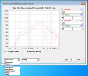
Your point concerning directional bass arrays for use outdoors is well taken. When Hornresp 5040 updated the Wizard for dipoles (H-frame, U-frame, flat baffle), the ability to plot on-axis pressure response on either side of the dipole was incorporated. I would have preferred to include a directivity polar plot for a selected frequency(see attached example for U-frame) rather than 2 on-axis pressure response points. But at the time, DMcBean felt it was not warranted and considered the 2 points a good compromise between providing useful information vs. complexity. Perhaps it might be revisited in the future if there is enough interest. Note that the bold portion of the pressure response curve is the portion of the curve where the point source modeling is considered appropriate/accurate.There are however examples of the low frequency outputs of two sources deliberately set a specific distance from each other to reduce output levels in one direction while increasing it in the other. End-fire subwoofer arrays for example. And the effect isn't only noticeable when the listening position is close to the subwoofers.
The LF directivity of, say, the Bose Wave Cannon could be similarly modeled, or any other compound source like an unwrapped version of your MTLT. Currently, if it is not of H-frame or U-frame geometry you would need to export magnitude/phase response for the individual sources and create the LF polar plot in Excel. I could clean up and post a version of my spreadsheet for doing this if there is interest.
Attachments
Hello David,
Using last release. When I go to MEH wizard in Tools, I get the ‘run time error 380. Invalid property value’ message. I double checked all values, the ME1 entry if changed to normal Nd works ok.
Do you know how to track the problem?
Thanks!
David I'm having this exact problem with ME1 & ME2 records. Everything else in HR seems to be working normally. I only get this error once I try to use the ME wizard. I've tried old records and creating new ones with the same result. Perhaps I'm overlooking something obvious. Can you see if this record will run for you?
View attachment ME1TestMF.txt
View attachment ME1TestND.txt
- Home
- Loudspeakers
- Subwoofers
- Hornresp