Hi Brian,
Too much work - it's not going to happen!
What could perhaps be done is to:
1. Swap the chambers and ports over in the BP6 models.
2. Automatically switch to the BP4 model when Ap2 is set to 0.10 or less in the BP6 models.
Would this be an acceptable compromise?
Kind regards,
David
Sounds good. Only the BP6S model should need to have the volumes swapped though. BP6P seems fine as it is.
As for switching to the BP4 mode, Setting Ap2 to 0.00 in the sim could work as the trigger.
Try pressing the F8 function key in edit mode to reset the filter parameters values to their default values.
F8 did the trick, thanks.
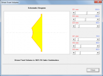
hornresp has a "driver volume" feature.
Just to clarify - the Hornresp 'Driver Front Volume' tool calculates the effective air volume between the driver diaphragm and the front plane of the driver, which can be taken into account when dimensioning a throat chamber. The tool does not calculate the total volume occupied by the driver.
Attachments
Hi Brian,
As part of the exercise I intended altering the BP4, BP6S and BP6P schematic diagrams to make them more consistent. Strictly speaking, the BP6P model should then also be modified internally to reflect the change.
Changing the Ap2 slider to accept a zero value would require a surprising amount of work. Not sure it is going to happen - 0.10 or less is more likely at this stage.
To further reduce the amount of work required, could you live with manually updating existing BP6S records (and ideally also BP6P records) rather than having them updated automatically by Hornresp?
Kind regards,
David
BP6P seems fine as it is.
As part of the exercise I intended altering the BP4, BP6S and BP6P schematic diagrams to make them more consistent. Strictly speaking, the BP6P model should then also be modified internally to reflect the change.
Setting Ap2 to 0.00 in the sim could work as the trigger.
Changing the Ap2 slider to accept a zero value would require a surprising amount of work. Not sure it is going to happen - 0.10 or less is more likely at this stage.
To further reduce the amount of work required, could you live with manually updating existing BP6S records (and ideally also BP6P records) rather than having them updated automatically by Hornresp?
Kind regards,
David
Changing the Ap2 slider to accept a zero value would require a surprising amount of work. Not sure it is going to happen - 0.10 or less is more likely at this stage.
How about if Lp2 is set to zero?
If that also requires a lot of work, then there's no need to bother - as long as the modeling shows that a BP6 with a minuscule vent for one chamber should have a response that's almost identical to a BP4 with that chamber being sealed.
To further reduce the amount of work required, could you live with manually updating existing BP6S records (and ideally also BP6P records) rather than having them updated automatically by Hornresp?
Sounds fine to me....
Hi Brian,
Setting Lp2 to zero would require the same amount of work as for Ap2. Besides, I have other additional functionality in mind for Lp2") .
.
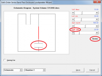
Setting the Ap2 slider to its minimum value will remove port tube 2 entirely, and the schematic will change accordingly to show this. The response will be identical to that of a BP4 enclosure.
Excellent. If everything goes according to plan, I hope to release the update some time tomorrow.
Kind regards,
David
How about if Lp2 is set to zero?
Setting Lp2 to zero would require the same amount of work as for Ap2. Besides, I have other additional functionality in mind for Lp2
.If that also requires a lot of work, then there's no need to bother - as long as the modeling shows that a BP6 with a minuscule vent for one chamber should have a response that's almost identical to a BP4 with that chamber being sealed.
Setting the Ap2 slider to its minimum value will remove port tube 2 entirely, and the schematic will change accordingly to show this. The response will be identical to that of a BP4 enclosure.
Sounds fine to me....
Excellent. If everything goes according to plan, I hope to release the update some time tomorrow.
Kind regards,
David
Hornresp Update 4830-181027
Hi Everyone,
CHANGE 1
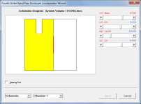
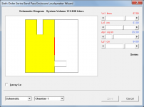
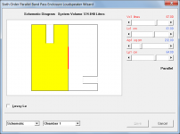
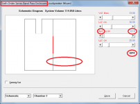
The BP4, BP6S and BP6P configurations and inputs have now been made consistent, as suggested by Brian in Post #8742. Attachments 1 to 3 refer.
NOTE - As a result of the above change, existing BP6S records will need to be modified. Chamber 1 and port 1 parameter values should be swapped with those for chamber 2 and port 2.
CHANGE 2
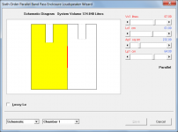
Setting the BP6S or BP6P Ap2 slider to its minimum value removes port tube 2 and simplifies the enclosure to a BP4 alignment. Attachment 4 refers.
CHANGE 3
Double-clicking the Lp2 slider in a BP6S enclosure specifies port tube 2 as unflanged at both ends. This will change the port tube 2 end correction and slightly alter the results. Attachment 5 refers.
Kind regards,
David
Hi Everyone,
CHANGE 1
The BP4, BP6S and BP6P configurations and inputs have now been made consistent, as suggested by Brian in Post #8742. Attachments 1 to 3 refer.
NOTE - As a result of the above change, existing BP6S records will need to be modified. Chamber 1 and port 1 parameter values should be swapped with those for chamber 2 and port 2.
CHANGE 2
Setting the BP6S or BP6P Ap2 slider to its minimum value removes port tube 2 and simplifies the enclosure to a BP4 alignment. Attachment 4 refers.
CHANGE 3
Double-clicking the Lp2 slider in a BP6S enclosure specifies port tube 2 as unflanged at both ends. This will change the port tube 2 end correction and slightly alter the results. Attachment 5 refers.
Kind regards,
David
Attachments
Nice updates. My OCD is going off again though:
1. If there's a way to convert from 6th to 4th in the wizard, there should be a way to convert from 4th to 6th
2. In the diagram, when both volumes are vented to the outside, one vent is pictured orthogonal to the driver, while the other is pictured parallel to the driver. For the model to be consistent, both vents should be pictured parallel to the driver. When the vent is positioned orthogonal to the driver, the driver's position on the baffle makes a difference to the out of band "noise", and this difference can be predicted and can actually be used to eliminate some of it. For more information, see this thread: Another enigma with my "Enigma"
Interestingly enough I was able to come up with a6th order BP series and 6th order BP parallel alignments that both had the same passband and sensitivity, but different box sizes. The "Iron Law" does frown upon this. I'll mess around with it a bit more and publish the alignments if I haven't figured out why that's happening.
I got same kind of stuff, but if i remember, port velocity was the big different. And to add, if modeling a 6th order as TH with back and front chambers + port, S5 output segment allow shaping a bit better.Interestingly enough I was able to come up with a6th order BP series and 6th order BP parallel alignments that both had the same passband and sensitivity, but different box sizes. The "Iron Law" does frown upon this. I'll mess around with it a bit more and publish the alignments if I haven't figured out why that's happening.
Hi Brian,
I don't want Ap2 and Lp2 sliders included when a BP4 system is specified - too confusing. It's not going to happen.
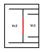
I liked the way that port tube 2 "jumped" from one side of chamber 2 to the other when a swap from BP6S to BP6P was made, but I can make the change if you really feel it would be worthwhile.
As far as the Hornresp BP6P simulation model is concerned, it doesn't matter where port tube 2 is positioned in chamber 2 - the chamber and port are assume to be connected in series:
BP6P acoustical circuit:
Radiator 1 - Port 1 - Chamber 1 - Driver - Chamber 2 - Port 2 - Radiator 2
Sanity check:
If Vc1 = Vc2, Lc1 = Lc2, Ap1 = Ap2 and Lp1 = Lp2 then port velocity 1 = port velocity 2 and the combined output is zero (shown as -990 dB in Hornresp).
Kind regards,
David
1. If there's a way to convert from 6th to 4th in the wizard, there should be a way to convert from 4th to 6th
I don't want Ap2 and Lp2 sliders included when a BP4 system is specified - too confusing. It's not going to happen
.2. In the diagram, when both volumes are vented to the outside, one vent is pictured orthogonal to the driver, while the other is pictured parallel to the driver. For the model to be consistent, both vents should be pictured parallel to the driver.
I liked the way that port tube 2 "jumped" from one side of chamber 2 to the other when a swap from BP6S to BP6P was made, but I can make the change if you really feel it would be worthwhile.
When the vent is positioned orthogonal to the driver, the driver's position on the baffle makes a difference to the out of band "noise", and this difference can be predicted and can actually be used to eliminate some of it.
As far as the Hornresp BP6P simulation model is concerned, it doesn't matter where port tube 2 is positioned in chamber 2 - the chamber and port are assume to be connected in series:
BP6P acoustical circuit:
Radiator 1 - Port 1 - Chamber 1 - Driver - Chamber 2 - Port 2 - Radiator 2
Sanity check:
If Vc1 = Vc2, Lc1 = Lc2, Ap1 = Ap2 and Lp1 = Lp2 then port velocity 1 = port velocity 2 and the combined output is zero (shown as -990 dB in Hornresp).
Kind regards,
David
Attachments
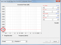
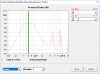
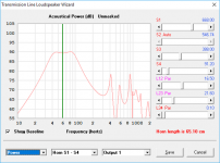
Fig 1. - My "Enigma" build, modelled using OD
Fig 2. - My "Enigma" build, modelled using BP4
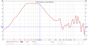
Fig 3. - Measured response of my Enigma build
While both BP4 and OD options get the shape of the passband at bass frequencies right, the OD model is more accurate at predicting the out of band frequency peaks. It's almost dead-on with the peak just above 400 Hz.
Note: the BP4 option doesn't seem to provide a means of exporting the predicted frequency response as an FRD file. If it could, I could import all three curves into REW to overlay them for a better comparison.
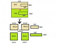
It's almost like the front chamber has to be described as
Vc1.1(Lc1.1) - Driver - Vc1.2(Lc1.2) - Ap1(Lp1) - Radiator
Where
Vc1 = Vc1.1+Vc1.2
Lc1 = Lc1.1+Lc1.2
Extending this to a BP6P, the rear chamber would be described as
Vc2.1(Lc2.1) - Driver - Vc2.2(Lc2.2) - Ap2(Lp2) - Radiator
Setting Vc1=Vc2, Lc=Lc2, Ap1=Ap2 and Lp1=Lp2 above should result in the same nulled response, so the sanity check works, UNLESS the driver is in a different position in the second chamber (i.e. Lc1.1 <> Lc2.1), in which case there should be a few peaks in the response at high frequencies.
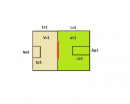
Of course this is only applicable where the driver is mounted orthogonal to the vent, which the second-to-last image describes. If it's mounted on the panel facing the vent, as pictured in the last image, then effectively Lc1.1 and Lc2.1 are both equal to zero and the current model in Hornresp should accurate enough to predict behaviour at higher frequencies.
Fig 2. - My "Enigma" build, modelled using BP4
Fig 3. - Measured response of my Enigma build
While both BP4 and OD options get the shape of the passband at bass frequencies right, the OD model is more accurate at predicting the out of band frequency peaks. It's almost dead-on with the peak just above 400 Hz.
Note: the BP4 option doesn't seem to provide a means of exporting the predicted frequency response as an FRD file. If it could, I could import all three curves into REW to overlay them for a better comparison.
It's almost like the front chamber has to be described as
Vc1.1(Lc1.1) - Driver - Vc1.2(Lc1.2) - Ap1(Lp1) - Radiator
Where
Vc1 = Vc1.1+Vc1.2
Lc1 = Lc1.1+Lc1.2
Extending this to a BP6P, the rear chamber would be described as
Vc2.1(Lc2.1) - Driver - Vc2.2(Lc2.2) - Ap2(Lp2) - Radiator
Setting Vc1=Vc2, Lc=Lc2, Ap1=Ap2 and Lp1=Lp2 above should result in the same nulled response, so the sanity check works, UNLESS the driver is in a different position in the second chamber (i.e. Lc1.1 <> Lc2.1), in which case there should be a few peaks in the response at high frequencies.
Of course this is only applicable where the driver is mounted orthogonal to the vent, which the second-to-last image describes. If it's mounted on the panel facing the vent, as pictured in the last image, then effectively Lc1.1 and Lc2.1 are both equal to zero and the current model in Hornresp should accurate enough to predict behaviour at higher frequencies.
Attachments
Last edited:
Hi Brian,
Refining the Hornresp bandpass models to allow for drivers to be offset would introduce a whole new level of complexity, not only in the simulation models, but also in the operation of the loudspeaker wizard itself. I simply cannot justify the work involved, particularly as the improvement would seemingly only apply at higher frequencies.
Not that it affects the results in any way, but I will however change the position of the port tube 2 in the BP6P schematic, as suggested by you. It will be done in the next update.
The band pass and multiple entry horn loudspeaker wizards do not allow for results to be exported. I will have a look to see how much work would be required to change this.
Kind regards,
David
While both BP4 and OD options get the shape of the passband at bass frequencies right, the OD model is more accurate at predicting the out of band frequency peaks.
Refining the Hornresp bandpass models to allow for drivers to be offset would introduce a whole new level of complexity, not only in the simulation models, but also in the operation of the loudspeaker wizard itself. I simply cannot justify the work involved, particularly as the improvement would seemingly only apply at higher frequencies.
Not that it affects the results in any way, but I will however change the position of the port tube 2 in the BP6P schematic, as suggested by you. It will be done in the next update.
Note: the BP4 option doesn't seem to provide a means of exporting the predicted frequency response as an FRD file..
The band pass and multiple entry horn loudspeaker wizards do not allow for results to be exported. I will have a look to see how much work would be required to change this.
Kind regards,
David
Attachments
Why would someone build a BP6P like your last picture?
I don't think anyone would, but that's the closest topology to the way that Hornresp is simming a BP6P enclosure, with no driver "offset".
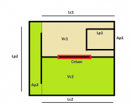
Most usually build the BP6P enclosure with the vents on the same side, which in turn means that the driver is likely mounted on a panel adjacent to the vents, not opposite it, and even if you manage to get the vents on the same panel and the driver on the opposite panel (see image below for example), you'll still end up with the driver at an offset, and Hornresp's predictions for the out of band peaks will be off. Depending on how large the box is, or how large the vents are, this could also possibly impact the upper frequency response in the passband.
Attachments
Refining the Hornresp bandpass models to allow for drivers to be offset would introduce a whole new level of complexity, not only in the simulation models, but also in the operation of the loudspeaker wizard itself. I simply cannot justify the work involved, particularly as the improvement would seemingly only apply at higher frequencies.
Drat. Based on the "luck" I had with the Enigma design, with its offset driver managing to null out a good portion of the out of band frequency peaks, I was hoping to repeat that success with a properly sim'd BP6S or BP6P alignment
. Note that only one extra input term is required, if the driver offset is assumed to the same for both front and rear volumes, e.g. Vc1.1 and Vc1.2 can be derived from Vc1, Lc1 and the offset, ditto for Vc2.1 and Vc2.2. But iof course even if those values can be derived from using one extra parameter, the calculations are likely going to be a lot more complex.Oh well, I think my "OD" sim "ratch" might be good enough to predict where the null from the driver's offset will fall in any case, so I could use that to fine tune the driver position.
I'm still mulling about what my next POC project is going to be, but I'm kind of leaning towards a BP6S alignment that looks a bit like the attached image. I suspect it's going to be a two-stage process - design the BP using the BP6S option, and then transfer the front chamber dimensions to an OD sim and use that to fine-tune the driver's position in the chamber. The aim would be to not only get a good bass passband, but find the best geometry to suppress the worst of the out of band "hash".
Attachments
Brian is smoke coming out of your ears from all this heavy thinking?
He's a man on a mission.

- Home
- Loudspeakers
- Subwoofers
- Hornresp