was modelling a 4th order bandpass as mentioned above and wanted to do a very large throat chamber...over 1,000,000 cc for a mobile application.
is there a wy to do this?
its a multiple driver application for high spl output, think dbDragracing and 150+db.
thinking of a 2:1 ratio 4th order for 4 15" drivers.
is there a wy to do this?
its a multiple driver application for high spl output, think dbDragracing and 150+db.
thinking of a 2:1 ratio 4th order for 4 15" drivers.
was modelling a 4th order bandpass as mentioned above and wanted to do a very large throat chamber...over 1,000,000 cc for a mobile application.
is there a wy to do this?
its a multiple driver application for high spl output, think dbDragracing and 150+db.
thinking of a 2:1 ratio 4th order for 4 15" drivers.
Hi Etocynned,
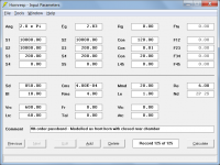
Model as shown in the attachments.
Kind regards,
David
Attachments
Multiple Entry Horn Wizard
Hello David,
I'm playing around with the Multiple Horn Entry Wizard trying to do a Synergy style simulation.
So far it looks good, however my tweeter response is somewhat garbled. I've tried using CD parameters from this thread:http://www.diyaudio.com/forums/multi-way/138637-modelling-compression-drivers.html.
I don't need a perfect response from the tweeter, just something that seems plausible.
When I use the wizard it gives me this response when calculating from the Input Parameters page:


Something is probably wrong as it has very low sensitivity, but that is fine.
When I run the wizard and choose Total Response in the drop down menu it looks like this:

So, something is wrong. Do you have any ideas?
I've attached the exported record files:
View attachment syn1-3.txt
View attachment syn2-3.txt
View attachment syn3-3.txt
Many regards
Daniel
Hello David,
I'm playing around with the Multiple Horn Entry Wizard trying to do a Synergy style simulation.
So far it looks good, however my tweeter response is somewhat garbled. I've tried using CD parameters from this thread:http://www.diyaudio.com/forums/multi-way/138637-modelling-compression-drivers.html.
I don't need a perfect response from the tweeter, just something that seems plausible.
When I use the wizard it gives me this response when calculating from the Input Parameters page:
Something is probably wrong as it has very low sensitivity, but that is fine.
When I run the wizard and choose Total Response in the drop down menu it looks like this:
So, something is wrong. Do you have any ideas?
I've attached the exported record files:
View attachment syn1-3.txt
View attachment syn2-3.txt
View attachment syn3-3.txt
Many regards
Daniel
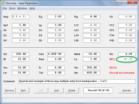
Hello Daniel. The first thing I noticed is in the top left hand corner. You are simulating the response in a reflection free environment. 4Pi. Normal loudspeaker simulation for standard application is done in a 2Pi environment. That will push up your efficiency to a much more realistic level.
A 4pi load should be fine if that is how the system is placed. 2pi would mean you're mounting the system in-wall which I doubt anyone does.
When I simulate compression drivers in 4pi on a horn, I usually see around 105dB for ~1W input for the power response (response not including directivity - output on axis will be higher). You are modeling a nominally 16 ohm driver, so you are simulating more like 0.5W input. What driver are you trying to simulate? I'd say your BL is probably low and your Mmd is high given the Sd you have in there unless it's a really bad driver. Also your Vtc, throat chamber volume, is not 0 if it's a normal compression driver.
When I simulate compression drivers in 4pi on a horn, I usually see around 105dB for ~1W input for the power response (response not including directivity - output on axis will be higher). You are modeling a nominally 16 ohm driver, so you are simulating more like 0.5W input. What driver are you trying to simulate? I'd say your BL is probably low and your Mmd is high given the Sd you have in there unless it's a really bad driver. Also your Vtc, throat chamber volume, is not 0 if it's a normal compression driver.
Last edited:
A 4pi load should be fine if that is how the system is placed. 2pi would mean you're mounting the system in-wall which I doubt anyone does.
When I simulate compression drivers in 4pi on a horn, I usually see around 105dB for ~1W input for the power response (response not including directivity - output on axis will be higher). You are modeling a nominally 16 ohm driver, so you are simulating more like 0.5W input. What driver are you trying to simulate? I'd say your BL is probably low and your Mmd is high given the Sd you have in there unless it's a really bad driver. Also your Vtc, throat chamber volume, is not 0 if it's a normal compression driver.
4pi is on purpose
I see that I pasted the wrong input parameters. I'm not set on a particular driver yet, but I'm trying to use these parameters:
...
The only input parameter values I have are for the 120 watt PA-D120N compression driver. The actual figures used by P.Audio in their Hornresp simulations were:
Sd = 34.00 sq cm
Bl = 8.00 tesla.m
Cms = 6.20E-05 m/newton
Rms = 0.74 newton.sec/m
Mmd = 2.77 gm
Le = 0.35 millihenrys
Re = 4.70 ohms
Vrc = 0.10 litres
Lrc = 0.10 cm
Fr = 0.00 rayls/cm
Tal = 0.00 cm
Vtc = 0.24 cc
Atc = 34.00 sq cm
...
But the problem is the same as before; the Nd input list still shows "nonsense" via the Multiple Entry Horn Wizard.
Daniel
What is nonsense? The combined response? When you have helmholtz resonators in parallel with the horn's impedance as seen by the tweeter, the possibility exists to cause peaks and notches in the response of the system. When there's no damping simulated, those peaks and notches can be very nasty looking.
What is nonsense? The combined response? When you have helmholtz resonators in parallel with the horn's impedance as seen by the tweeter, the possibility exists to cause peaks and notches in the response of the system. When there's no damping simulated, those peaks and notches can be very nasty looking.
Apparently the nonsense was purely on my side. I went in and decreased all the ports and chambers to as close to zero as possible and the response lost most, if not all of its nastiness.
I appreciate the hint
-Daniel
So, something is wrong. Do you have any ideas?
Hi Daniel,
I gather from your most recent comments that things have now been sorted out, thanks to John, and that your simulation results are starting to make more sense. As you have discovered, the performance of a Synergy / Unity type loudspeaker is extremely sensitive to parameter value changes - they can be difficult beasts to tame
") .
.Kind regards,
David
Hornresp Update 4050-170420
Hi Everyone,
CHANGE 1
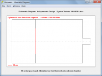
The chamber and port tube elements in the BP6, BP8 and ABC simulation models have been changed from parallel to series connections so that all Hornresp models now have the same network topology, and are entirely consistent. Predicted results at the higher frequencies will be slightly different to those calculated previously, but whether or not they are more accurate will depend upon the actual physical construction of the band pass loudspeaker enclosure system, and the relative positions of the chambers and port tubes in the design.
CHANGE 2
After the "custom designs retained when window resolution changed" enhancement was added to the Wavefront Simulator tool in the previous update, the Add Border and Clear Border options no longer operated correctly when the resolution was changed. This problem now been fixed.
Kind regards,
David
Hi Everyone,
CHANGE 1
The chamber and port tube elements in the BP6, BP8 and ABC simulation models have been changed from parallel to series connections so that all Hornresp models now have the same network topology, and are entirely consistent. Predicted results at the higher frequencies will be slightly different to those calculated previously, but whether or not they are more accurate will depend upon the actual physical construction of the band pass loudspeaker enclosure system, and the relative positions of the chambers and port tubes in the design.
CHANGE 2
After the "custom designs retained when window resolution changed" enhancement was added to the Wavefront Simulator tool in the previous update, the Add Border and Clear Border options no longer operated correctly when the resolution was changed. This problem now been fixed.
Kind regards,
David
This problem now been fixed.
Should read: "This problem HAS now been fixed."
.Thanks for your prompt bug swatting!
Hi Mark,
It seems that just when I think everything is finally working as intended, I always manage to find something else that requires attention
.Kind regards,
David
Hi USRFobiwan,
Only if it can be specified using the standard available Hornresp driver input parameters.
The same way as for any other design - just specify multiple drivers, as shown in the attachment.
Kind regards,
David
Can i simulate a coaxial Compression Driver.
Only if it can be specified using the standard available Hornresp driver input parameters.
How can I sim multiple large woofer drivers, for example 6x 15".
The same way as for any other design - just specify multiple drivers, as shown in the attachment.
Kind regards,
David
Attachments
Understanding acoustical impedance graph
Hello.
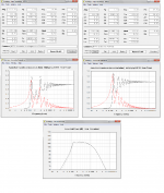
I'm modelling a midbass horn. Below is the comparison of a conical dual expansion vs a tractrix, both with the same drivers, same S1 and mouth size, same length. The frequency responses are very similar, with the tractrix showing smoother, but the differences are quite small considering the effect the room will have at these frequencies. Obviously the conical is much easier to build.
So I look at the acoustical impedance, hoping to be able to derive conclusions about how these differ. What do these tell me, though?
How do I interpret the graphs? What's the red line and what's the black one?
Thank you in advance!
Hello.
I'm modelling a midbass horn. Below is the comparison of a conical dual expansion vs a tractrix, both with the same drivers, same S1 and mouth size, same length. The frequency responses are very similar, with the tractrix showing smoother, but the differences are quite small considering the effect the room will have at these frequencies. Obviously the conical is much easier to build.
So I look at the acoustical impedance, hoping to be able to derive conclusions about how these differ. What do these tell me, though?
How do I interpret the graphs? What's the red line and what's the black one?
Thank you in advance!
Attachments
Hi LewinskiH01,
The throat acoustical impedance chart shows how well the horn system couples to the space into which it radiates. The less mismatch there is at the horn mouth, the smaller the reflections, and therefore the lower the amplitude of the ripples in the throat impedance. In the limiting case of an infinite horn, there are no ripples. Different horn types have different characteristic throat impedance curves.
The red line shows the throat acoustical reactance, the black line shows the throat acoustical resistance. The Hornresp Sample tool can be used to confirm this.
If you would like to know more about the significance of horn throat impedance, Google:
Horn Theory: An Introduction, Part 1
Dr Kolbrek's excellent article covers the subject very well indeed.
Kind regards,
David
So I look at the acoustical impedance, hoping to be able to derive conclusions about how these differ. What do these tell me, though?
The throat acoustical impedance chart shows how well the horn system couples to the space into which it radiates. The less mismatch there is at the horn mouth, the smaller the reflections, and therefore the lower the amplitude of the ripples in the throat impedance. In the limiting case of an infinite horn, there are no ripples. Different horn types have different characteristic throat impedance curves.
How do I interpret the graphs? What's the red line and what's the black one?
The red line shows the throat acoustical reactance, the black line shows the throat acoustical resistance. The Hornresp Sample tool can be used to confirm this.
If you would like to know more about the significance of horn throat impedance, Google:
Horn Theory: An Introduction, Part 1
Dr Kolbrek's excellent article covers the subject very well indeed.
Kind regards,
David
- Home
- Loudspeakers
- Subwoofers
- Hornresp