Now based on the functionality of the Resize Wizard and what I've been able to do with it manually I can't help but think that Hornresp could use this foundation to actually display response down to 1 hz.
Of course I don't know anything about programming but this is how I imagine it working:
On the inputs window in the tools menu you could have an entry giving the option for "graph low limit 10 hz" and it would function as usual or the option for "graph low limit 1 hz" and it would do the following things:
Hornresp would automatically and behind the scenes resize the design to 0.1.
Hornresp would calculate and show a 1 - 2000 hz range in the graphs that show frequency response instead of the usual 10 - 20000 hz range.
Hornresp would automatically correct for the graphs that need correcting like velocity, group delay, diaphragm pressure, etc that will be off by a factor of 10.
Hornresp would do all this behind the scenes, so the schematic would report the original volume (unresized) and all the graphs would be accurate for the 10x lower response.
Like I said, I know nothing of programming but it would seem to only require maybe only 5 or 10 commands and a reformatting of the numbers on the frequency legend.
Or maybe it's much more complicated than that, I don't know.
@ David McBean
I thought you might like to know that HR was featured & used in here
https://soundforums.net/forum/pro-a...oking-at-speakers-and-rooms-review-of-apl-tda Whether or not he also used HR for the "multiple entry conical horn" Synergy, i'm not sure. But his use of the term MECH sure sounds like it")
I designed the speaker, including the bandpass chambers for the MEH, using HR, but most of my sims were done before the multiple entry wizard was released.
If you look at this thread you might see a resemblance to the speaker picture in the article:
http://www.diyaudio.com/forums/multi-way/291160-my-synergy-corner-horn-bass-bins.html
Jack
Hi just a guy,
Thanks for your comments.
The Resize input form is titled "Resize Baseline Design". I felt that this was sufficient indication.
If baseline values are not locked in, the parameter values "compound" with each resize. This can prove to be quite confusing.
This is because the resize factor specified would result in resized parameter values less than 0.01 and/or greater than 99999.99 (999999.9 in the case of Vtc), thus exceeding the Hornresp limits.
Kind regards,
David
Thanks for your comments.
Or it could just give a warning on each subsequent resize attempt that it is still using the baseline parameters.
The Resize input form is titled "Resize Baseline Design". I felt that this was sufficient indication.
Or the best solution would be to not lock in baseline parameters at all, so subsequent resizes would be fully functional.
If baseline values are not locked in, the parameter values "compound" with each resize. This can prove to be quite confusing.
Some of my files would give error "Resize factor can not be less than 1.01" and error "Resize factor can not be greater than 4.99. Both a low limit and a high limit for the affected files.
This is because the resize factor specified would result in resized parameter values less than 0.01 and/or greater than 99999.99 (999999.9 in the case of Vtc), thus exceeding the Hornresp limits.
Kind regards,
David
Driver xmax is equal in both versions.
Hi just a guy,
Actually, Xmax' = Xmax * Scale
I did not include this particular conversion in the Hornresp Resize Wizard tool because it was easier to compare frequency-shifted Maximum SPL responses without it. On second thoughts though perhaps it should be there, along with Pmax1 = Pmax * Scale. I will probably make the changes in the next update.
Note also that the some of the scaling formulas get more complicated when Re is changed along with the Resize factor.
Kind regards,
David
Or maybe it's much more complicated than that, I don't know.
Hi just a guy,
I can certainly think of much easier ways to do it, but it is still not going to happen, as it would cause all sorts of other issues for me
.Kind regards,
David
I designed the speaker, including the bandpass chambers for the MEH, using HR, but most of my sims were done before the multiple entry wizard was released.
If you look at this thread you might see a resemblance to the speaker picture in the article:
http://www.diyaudio.com/forums/multi-way/291160-my-synergy-corner-horn-bass-bins.html
Jack
Thanks Jack and Zero D.
Kind regards,
David
I can do it and have done it before.
Hi Mark,
It is interesting that the rescaling method suggested by Bjørn to determine the response below 10Hz can also be used in reverse to find the system suited to the driver you specified.
Procedure:
Step 1 - Use the Resize Wizard tool with a resize factor of 10 to rescale the driver parameters.
Step 2 - Use the System Design With Driver tool to specify the rescaled system.
Step 3 - Divide lengths by 10 ^ 1, areas by 10 ^ 2 and volumes by 10 ^ 3 to find the parameter values for the desired unscaled system.
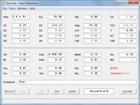
Given the following original values:
Ang = 2.0 * Pi
Sd = 5.30
Bl = 2.46
Cms = 4.99E-04
Rms = 0.32
Mmd = 0.14
Le = 0.01
Re = 6.70
Nd = 1
After Steps 1 and 2:
S1 = 28.68
S2 = 17412.87
L12 (Hyp) = 345.84
T = 0.85
Vrc = 2.93
Lrc = 5.52
Vtc = 94.19
Atc = 530.00
After Step 3:
System values suited to original unscaled driver are:
S1 = 0.29
S2 = 174.13
L12 (Hyp) = 34.58
T = 0.85
Vrc = 0.00 (actually 2.93 / 1000 = 0.0029, as previously advised)
Lrc = 0.55
Vtc = 0.09
Atc = 5.30
Attachments 1 and 2 refer (Value specified for Vrc is 0.01)
Kind regards,
David
Attachments
Hi Mark,
It is interesting that the rescaling method suggested by Bjørn to determine the response below 10Hz can also be used in reverse to find the system suited to the driver you specified.
Thanks for the alternate method David. I will try it.
What I failed to type in the second example I posted was that it was generated in 2014 using exactly the same method that failed to work this time around.
I used the design from driver data wizard, and changed the horn from Hypex to LeCleach. Played around with it and it will still load and function properly.
No problems.
So something in the past three years has changed. Not sure what it is.
What I failed to type in the second example I posted was that it was generated in 2014 using exactly the same method that failed to work this time around.
Hi Mark,
As far as I can recall, no changes have been made to the System Design tool in the past three years. Why the results should now be different is a real mystery to me.
Kind regards,
David
I did not include this particular conversion in the Hornresp Resize Wizard tool because it was easier to compare frequency-shifted Maximum SPL responses without it. On second thoughts though perhaps it should be there, along with Pmax1 = Pmax * Scale.
I have now remembered the main reason why Pmax and Xmax were not resized. It would have created problems in deciding when and when not to permanently save modified Pmax and Xmax values.
I will probably make the changes in the next update.
The Pmax and Xmax changes will now not be made.
Or the best solution would be to not lock in baseline parameters at all, so subsequent resizes would be fully functional.
Hi just a guy,
I suspect that you may be using the Resize Wizard in ways that I never envisaged
.If the baseline method was optional rather than mandatory, would that make things easier for you?
Kind regards,
David
I have now remembered the main reason why Pmax and Xmax were not resized. It would have created problems in deciding when and when not to permanently save modified Pmax and Xmax values.
The Pmax and Xmax changes will now not be made.
Hi just a guy,
I suspect that you may be using the Resize Wizard in ways that I never envisaged
If the baseline method was optional rather than mandatory, would that make things easier for you?
Kind regards,
David
It might help if the baseline was optional. My main issue is that it seems really weird for the wizard to still be available and for it to run through the steps on subsequent resize attempts yet it fails to calculate what you asked it to. This seems very odd and I didn't even realize it wasn't doing what I asked until after a few subsequent attempts.
Making the wizard functional for another attempt currently requires getting rid of the baseline, which is easy enough, I just go to the previous Hornresp file and then back again, hit EDIT and it's ready to go. So it's simple enough to get around the issue and it's not a big problem; the wizard behavior itself would seem to be the bigger issue.
I think I would prefer if the baseline method was not used, my second preference would be to make it optional as you mentioned.
About pmax and xmax - as long as I know what to do with them I can work with it.
This makes for a lot of things to remember now when using the Resize Wizard for frequency scaling the graph to a 1 hz lower limit.
Pmax (and the driver power window), xmax (and the excursion window), group delay, velocity and cone pressure all need to be scaled manually (mentally) after running the sim when using the resize wizard for frequency scaling. Did I miss any? Any other graphs need rescaling?
I think I would prefer if the baseline method was not used, my second preference would be to make it optional as you mentioned.
Before making a decision either way, I would be interested in feedback from other users.
Should the Resize Wizard tool baseline functionality be removed completely, or should it be retained, but optional?
Did I miss any? Any other graphs need rescaling?
Hi just a guy,
I haven't checked the implications of using the Resize Wizard to evaluate responses below 10Hz.
I will leave it to you to identify the charts that need rescaling
.Kind regards,
David
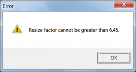
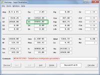
I was not able to figure out the reason for the upper limit on this sim (Resize factor can not be greater than 4.99)
To find the reason for the limit simply enter 4.99 as the resize factor and check the input parameters to see which one is close to its upper limit.
To illustrate - The maximum resize factor for the default record is 6.45. Entering this value shows that the resized value of S3 is 99846.00, just below the permitted limit of 99999.99.
Attachments
A surprising behaviour of hornresp...
Hello David,
First, thank you so much for offering this elaborate tool, and such curteous & excellent support to go with it!
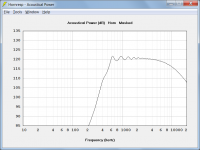
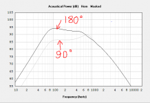
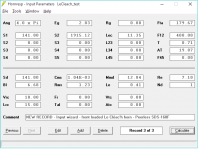
I have started using hornresp only recently, and I happened to notice that with a Le Cleac'h profile, if S2 is increased to where Fta goes past 90 degs, then the power response curve starts showing progressively higher values as Fta increases, reaching 9 dB increase at Fta = 180 degs (relative to Fta = 90 degs). This rise covers the whole freq spectrum below Fs, and the acoustical impedance curves show a similar trend. How should I interpret these results? (images & hornresp import txt record below)
I also have a question concerning exporting the Le Cleac'h profile for a rectangular horn while choosing conical width expansion. It seems that the height profile is simply computed from the equivalent Le Cleac'h axisymmetric horn, dividing the sectional area at each point along the central axis by the linearly expanding width to obtain the height at that point. If this is indeed the case, then I wonder if this reshape operation happens to preserve the original assumptions of equidistance of the successive wavefronts and their perpendicularity to the walls of the horn, or is it simply a good approximation?
Cheers,
Amir.
Hello David,
First, thank you so much for offering this elaborate tool, and such curteous & excellent support to go with it!
I have started using hornresp only recently, and I happened to notice that with a Le Cleac'h profile, if S2 is increased to where Fta goes past 90 degs, then the power response curve starts showing progressively higher values as Fta increases, reaching 9 dB increase at Fta = 180 degs (relative to Fta = 90 degs). This rise covers the whole freq spectrum below Fs, and the acoustical impedance curves show a similar trend. How should I interpret these results? (images & hornresp import txt record below)
I also have a question concerning exporting the Le Cleac'h profile for a rectangular horn while choosing conical width expansion. It seems that the height profile is simply computed from the equivalent Le Cleac'h axisymmetric horn, dividing the sectional area at each point along the central axis by the linearly expanding width to obtain the height at that point. If this is indeed the case, then I wonder if this reshape operation happens to preserve the original assumptions of equidistance of the successive wavefronts and their perpendicularity to the walls of the horn, or is it simply a good approximation?
Cheers,
Amir.
Attachments
Hi Amir,
Under certain conditions (and particularly in the case of relatively short horns with reasonably large throats) the Hornresp Le Cléac'h horn isophase wavefront simulation model tends to over-emphasize the effect of increasing the mouth flare tangent angle Fta beyond 90 degrees. For your 180 degree horn example, I would expect the actual performance to lie somewhere between the 90 and 180 degree predicted responses shown in your chart screenprint attachment. While the Hornresp model is not perfect, a more rigorous finite element analysis approach would take a relatively long time to produce results that are currently provided in a matter of seconds.
Correct.
It is simply an approximation. The most accurate Le Cléac'h horn to build is an axisymmetric one, using the Hornresp 'Exact Profile' option.
Kind regards,
David
How should I interpret these results?
Under certain conditions (and particularly in the case of relatively short horns with reasonably large throats) the Hornresp Le Cléac'h horn isophase wavefront simulation model tends to over-emphasize the effect of increasing the mouth flare tangent angle Fta beyond 90 degrees. For your 180 degree horn example, I would expect the actual performance to lie somewhere between the 90 and 180 degree predicted responses shown in your chart screenprint attachment. While the Hornresp model is not perfect, a more rigorous finite element analysis approach would take a relatively long time to produce results that are currently provided in a matter of seconds.
It seems that the height profile is simply computed from the equivalent Le Cleac'h axisymmetric horn, dividing the sectional area at each point along the central axis by the linearly expanding width to obtain the height at that point.
Correct.
If this is indeed the case, then I wonder if this reshape operation happens to preserve the original assumptions of equidistance of the successive wavefronts and their perpendicularity to the walls of the horn, or is it simply a good approximation?
It is simply an approximation. The most accurate Le Cléac'h horn to build is an axisymmetric one, using the Hornresp 'Exact Profile' option.
Kind regards,
David
Before making a decision either way, I would be interested in feedback from other users.
In the absence of any further feedback, the Resize Wizard tool baseline functionality will be removed, as suggested by 'just a guy'.
The change will be made in the next update.
Why can't Rg be made negative? This would be quite helpful for active designs using specialized amplifiers. Of course Rg must be restricted to values greater than -Re (the total static DC resistance of the driver(s)), to something like 90% of -Re or so.
I know negative Rg can be factored into the T/S params just like positive Rg, but a direct input possibility would be nice, not needing to change driver params.
I know negative Rg can be factored into the T/S params just like positive Rg, but a direct input possibility would be nice, not needing to change driver params.
Last edited:
- Home
- Loudspeakers
- Subwoofers
- Hornresp