David:
Just a thought (that may be easy enough to implement) In the options dialog, add a 'automatic combined response' and if Ap/Lpt have values, combine the port response in the spl chart.
Just a usability suggestion.
My THANKS for a great application. (can't shout that one out loud enough)
Just a thought (that may be easy enough to implement) In the options dialog, add a 'automatic combined response' and if Ap/Lpt have values, combine the port response in the spl chart.
Just a usability suggestion.
My THANKS for a great application. (can't shout that one out loud enough)
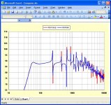
revintage said:When I read it -3dB in Hornresp is 45 and MJK is at least 50Hz. This means ca 10% diff.
Hi Lars,
Out of interest I compared the Hornresp and AkAbak power responses for your design example assuming half-space loading. As you can see from the attached screenprint, the low frequency roll-off points predicted by the two programs are identical - the Hornresp red trace is completely hidden beneath the AkAbak blue trace.
Kind regards,
David
Attachments
jbell said:In the options dialog, add a 'automatic combined response' and if Ap/Lpt have values, combine the port response in the spl chart.
Hi jbell,
Thanks for the suggestion. Implementation would not be as straightforward as it might seem, but I will certainly give it some thought. Please note that nothing is promised at this stage
") .
.Thanks again for the feedback.
Kind regards,
David
Double horn in one box????
How would I go about laying out two smaller horns in one box, driven by one driver and sharing one mouth.
Is it as simple as dividing the cross sectional area of one into two?
I'm thinking of 2-4 taps off the driver entry point, feeding 2-4 smaller compressed horn sections that would all meet later with the final horn stages in a tapped.
This way I have more space to work with to make snails etc to feed the horn,
Re: Double horn in one box????
Hi screamerusa,
If the two smaller horns are identical, then yes, it is that simple. The principle is used to good effect in the bifurcated Klipschorn design.
Kind regards,
David
screamersusa said:Is it as simple as dividing the cross sectional area of one into two?
Hi screamerusa,
If the two smaller horns are identical, then yes, it is that simple
. The principle is used to good effect in the bifurcated Klipschorn design.Kind regards,
David
G'day Jim and Syd
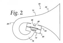
Despite being a good idea, I don't believe Helmholtz resonators are used on the front side of the driver in many (perhaps none) of Tom's commercial tapped horns. I believe this is probably due to construction complexity, and the difficulty in changing drivers, if necessary. There is a good chance they are used on the other side of the driver, though.
Cheers
William Cowan
Bill:
My thinking when I saw resonator, was that in a 115 style cabinet (magnet hanging in the mouth) that the helmholtz could eliminate some long path high frequency (100hz-ish on up) and would clean up the kick range with less constructive/destructive interference.
Seems worth playing with anyway, and was one of my nuggets of info gleaned from sitting down and reading patents.
jbell said:Is it an easy thing to add the ability to model both a rear chamber as well as a front chamber.
Hi jbell,
A rear chamber could be added to the Hornresp tapped horn model relatively easily. From testing I have done however, it would seem that having a chamber between the driver diaphragm and the entry point into the tapped horn near the mouth makes very little difference to the overall result. For that reason I did not bother to include the option in the production version of the program.
You can of course experiment with such a configuration using AkAbak, if you wish.
Kind regards,
David
S2 slider
Crazy request...
Any chance of adding an s2 slider and an align or lock button?
I've been tweaking s2 manually outside of the tapped horn wizard
to play with the 60-100hz dip associated with some drivers.
If there was an s2 slider this could be done in the wizard, a reset or auto align or lock would be nice to either reset to original s2 parameters based on s1/s3 or lock the offset such that you could tweak s1 and s3 in the same manner you can now with s2 following with the offset value applied. Breaking the rules basically.
The way you have the l3-l4 locks on pull down menus would probably be the best place for the lock/auto selection for s2.
2nd question. Whats the best way to compensate manually for the driver itself. I noticed that my inverted driver seems to invert the curve slightly in the middle range vs the hornresp prediction.
This was discovered after remeasuring a built cabinet and comparing the results against the original sim, post build sim, and actual test response. Not something I expect the program to do as I understand the flat plane approach. Perhaps I should be teating the cone as a chamber when firing into the horn throat, and subtracting it from the throat when the driver is inside the throat???
Thanks.
Re: S2 slider
Hi screamerusa,
Sorry - at this stage, there is very little chance.
Not sure - perhaps someone else might have some thoughts on this.
Kind regards,
David
Hi screamerusa,
screamersusa said:Any chance of adding an s2 slider and an align or lock button?
Sorry - at this stage, there is very little chance
.screamersusa said:Whats the best way to compensate manually for the driver itself.
Not sure - perhaps someone else might have some thoughts on this.
Kind regards,
David
Re: S2 slider
For sure if you want same-same response at least out to where half WL loading occurs in its HF BW you'll have to account for the driver's bulk in the initial expansion where it's typically only a fraction of the driver's Sd, Vas and the lack of it at the open end, i.e. preserve the expansion from the closed end onward, ergo two different layouts are ideally required for each driver orientation, especially with a large motor, high excursion one.
GM
screamersusa said:
Perhaps I should be teating the cone as a chamber when firing into the horn throat, and subtracting it from the throat when the driver is inside the throat???
For sure if you want same-same response at least out to where half WL loading occurs in its HF BW you'll have to account for the driver's bulk in the initial expansion where it's typically only a fraction of the driver's Sd, Vas and the lack of it at the open end, i.e. preserve the expansion from the closed end onward, ergo two different layouts are ideally required for each driver orientation, especially with a large motor, high excursion one.
GM
Hi David
I'm concerned that the maximum SPL calculations might be wrong. When I simulate a TH I get a dip in the maximum SPL at the upper impedance minimum where cone excursion is zero, I would expect to have a maximum here. Also, the maximum SPL at higher frequencies doesn't stack up with the efficiency+input power.
Can you explain this? It's almost as if you're using 1W into the actual impedance at each frequency instead of the nominal impedance...
Cheers
Ian
iand said:Hi David
I'm concerned that the maximum SPL calculations might be wrong. When I simulate a TH I get a dip in the maximum SPL at the upper impedance minimum where cone excursion is zero, I would expect to have a maximum here. Also, the maximum SPL at higher frequencies doesn't stack up with the efficiency+input power.
Can you explain this? It's almost as if you're using 1W into the actual impedance at each frequency instead of the nominal impedance...
Cheers
Ian
Hi Ian,
Happy New Year!
As detailed in the Hornresp Help file, the Maximum SPL tool displays the maximum sound pressure level in decibels that can be achieved at 1 metre without exceeding the rated thermal limited electrical input power Pmax or the diaphragm linear mean-to-peak displacement limit Xmax, versus frequency in hertz.
When calculating the power-limited response I assume an input power of Pmax watts into the actual loudspeaker impedance at each frequency. Why is this not correct?
Kind regards,
David
David McBean said:
Hi Ian,
Happy New Year!
As detailed in the Hornresp Help file, the Maximum SPL tool displays the maximum sound pressure level in decibels that can be achieved at 1 metre without exceeding the rated thermal limited electrical input power Pmax or the diaphragm linear mean-to-peak displacement limit Xmax, versus frequency in hertz.
When calculating the power-limited response I assume an input power of Pmax watts into the actual loudspeaker impedance at each frequency. Why is this not correct?
Kind regards,
David
You're correct in that this limits the actual thermal dissipation in the voice coil to the number specified. But I don't think thsi is sensible for speaker design for two reasons.
The first is that driver power rating is done on an "applied rms voltage into nominal impedance" basis, so an 8 ohm driver rated at 1250W rms will survive a 100V rms bandlimited pink noise signal. So the number that is put into Hornresp for thermal power handling is based on this, not 1250W thermal dissipation in the voice coil.
The second is that amplifiers are voltage output; so an amp rated at 1250W/8ohms will deliver 100V rms, it won't deliver higher voltage where the load impedance is higher. So output levels peaking at 140dB where the impedance is high might be OK from a theoretical point of view, are are not sensible in practice.
Whether the Pe figure is driver rating or amplifier power, it should be the output with an applied voltage equal to the power rating of either the driver or the amplifier -- but this means that Hornresp needs to know the nominal impedance, which it doesn't right now.
So for the maximum SPL calculation it would be much more sensible to specify Xmax and rms voltage (instead of Pe), since this is how both drivers and amplifiers are rated.
Cheers
Ian
- Home
- Loudspeakers
- Subwoofers
- Hornresp