catapult said:
Edit: all the sims are using the 10" vertical dimension of the QSC 90x60.
Humor us with the 6.5" 90° x 50° case, please, subject of this thread.
What 10", 90° round waveguide are you modeling?
Re: Re: Criteria:
For the past couple of weeks I've been working on a set of severely compromised horns. The vertical angle is very VERY narrow.
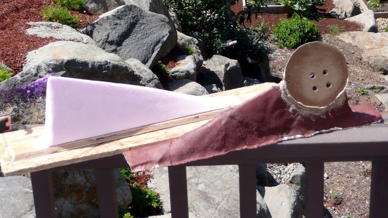
Here's what they look like.
When I first messed around with the HOM-killing foam, I noticed that it improved the sound of a horn more than a waveguide.
My theory is that the difference is more audible because the horn has more HOMs.
On this new set of horns, I've noted the same thing, but the difference is even more dramatic. Without the foam, the horns have a "hashy" character in the upper treble. With the foam, much of this character goes away.
The most notable difference, by far, is that I always turn up the volume after the foam is in the horn. I can't explain why this is. With the foam, the speaker just begs to be played loudly.
I've done polar measurements before and after, and the difference in frequency response is about 3db at 2khz and 1db at 500hz.
How many speakers have you heard that use this technology, and what was your opinion on how they sounded?
TrueSound said:
It is true the JBL is the better constant directivity device based on the response plots.
The question is - Why do you care if "Gedlee" endorses it?
Why would a manufacture endorse something that is a fraction of the cost of what they sell?
I think you've clearly made your point, and so has Gedlee.
I'm still wondering how the manufacture measures HOM. I don't think that will be done by them for the same reasons.
For the past couple of weeks I've been working on a set of severely compromised horns. The vertical angle is very VERY narrow.
Here's what they look like.
When I first messed around with the HOM-killing foam, I noticed that it improved the sound of a horn more than a waveguide.
My theory is that the difference is more audible because the horn has more HOMs.
On this new set of horns, I've noted the same thing, but the difference is even more dramatic. Without the foam, the horns have a "hashy" character in the upper treble. With the foam, much of this character goes away.
The most notable difference, by far, is that I always turn up the volume after the foam is in the horn. I can't explain why this is. With the foam, the speaker just begs to be played loudly.
I've done polar measurements before and after, and the difference in frequency response is about 3db at 2khz and 1db at 500hz.
How many speakers have you heard that use this technology, and what was your opinion on how they sounded?
col said:second photo down:
http://www.htguide.com/forum/showthread.php4?t=34341
looks nicely done, would love to compare to my round waveguide/Mid. The Econowave I had didn't come anywhere near close and the comp driver was about 4 times as expensive. I'm wondering how much difference the roundovers make?
col.
That looks promising!
ZilchLab said:Humor us with the 6.5" 90° x 50° case, please, subject of this thread.
What 10", 90° round waveguide are you modeling?
Sure, what crossover frequency and acoustical (not electrical) slope?
The 10" is a generic 90 degree horn based on a text file I built. LspCAD can use files like these for off-axis sims. I put a little more effort into the 90x60, picking some numbers off Brandon's measurements. It would help if you'd build me one for the econowave. You can include as many frequencies and angles as you want. Otherwise I'll use the generic values commented out with //. LspCAD will interpolate values not included.
90x90
// 30 7.5:0 15:-6 90:-72
// 40 7.5:0 20:-6 90:-43
// 50 7.5:0 25:-6 90:-30
// 60 7.5:0 30:-6 90:-24
// 70 7.5:0 35:-6 90:-19
// 80 7.5:0 40:-6 90:-16
// 90 7.5:0 45:-6 90:-14
// 100 7.5:0 50:-6 90:-13
// 110 7.5:0 55:-6 90:-11
// 120 7.5:0 60:-6 90:-10
F:100
H: 15:0
V: 15:0
F:800
H: 15:0
V: 15:0
F:1500
H: 7.5:0 45:-6 90:-14
V: 7.5:0 45:-6 90:-14
F:16000
H: 7.5:0 30:-6 90:-24
V: 7.5:0 30:-6 90:-24
90x60
F:100
H: 15:0
V: 15:0
F:500
H: 15:0
V: 15:0
F:1000
H: 7.5:0 45:-3 67:-5
V: 7.5:0 30:-1 67:-3
F:2000
H: 7.5:0 45:-6 90:-14
V: 7.5:0 30:-6 90:-10
F:16000
H: 7.5:0 30:-6 90:-24
V: 7.5:0 20:-6 90:-43
From Earl's measurements, in 7.5° increments?
Vertical:
http://www.diyaudio.com/forums/attachment.php?s=&postid=1838011&stamp=1243376765
Horizontal:
http://www.diyaudio.com/forums/attachment.php?s=&postid=1839220&stamp=1243468708
To keep things comparable, LR4 @ 1.3 and 1.6 kHz, w/10" and 12" woofers....
Vertical:
http://www.diyaudio.com/forums/attachment.php?s=&postid=1838011&stamp=1243376765
Horizontal:
http://www.diyaudio.com/forums/attachment.php?s=&postid=1839220&stamp=1243468708
To keep things comparable, LR4 @ 1.3 and 1.6 kHz, w/10" and 12" woofers....
Okay Zilch, don't say I never did anything for you. ") Here's the file I used based on Earl's curves.
Here's the file I used based on Earl's curves.
F:100
H: 15:0
V: 15:0
F:500
H: 15:0
V: 15:0
F:1000
H: 7.5:0 90:-9
V: 7.5:0 90:-9
F:2000
H: 7.5:0 45:-6 90:-17
V: 7.5:0 22.5:-3 90:-18
F:16000
H: 7.5:0 45:-10 90:-28
V: 7.5:0 22.5:-6 90:-28
Econowave with 12" woofer and LR4-1600
Here's the file I used based on Earl's curves.F:100
H: 15:0
V: 15:0
F:500
H: 15:0
V: 15:0
F:1000
H: 7.5:0 90:-9
V: 7.5:0 90:-9
F:2000
H: 7.5:0 45:-6 90:-17
V: 7.5:0 22.5:-3 90:-18
F:16000
H: 7.5:0 45:-10 90:-28
V: 7.5:0 22.5:-6 90:-28
Econowave with 12" woofer and LR4-1600
Attachments


What software are you using to do the sim? Or are these measurements? The color shades do not seem to have enough contrast to see the pressure lines. Is it possible to show this?catapult said:Econowave with 10" woofer and LR4-1300
Let me interject a warm thanks for the knowledge/awareness y'all have provided me with.
I'm going to build a set of "these". My path is turning in augerpro's direction.
Would response "improve" if the horn (90 x 40) were more of an oval shape in section than the "squarish" QSC?
Thanks!
I'm going to build a set of "these". My path is turning in augerpro's direction.
Would response "improve" if the horn (90 x 40) were more of an oval shape in section than the "squarish" QSC?
Thanks!
soongsc said:What software are you using to do the sim? Or are these measurements? The color shades do not seem to have enough contrast to see the pressure lines. Is it possible to show this?
It's a sim done in LspCAD using 'perfect' drivers and a 'perfect' crossover transfer function. The horn's directivity is simulated with a text file and the woofer's directivity is simulated with piston diameter. You could use real measurements if you had them and a real crossover if you had the schematic. You can download the demo version and it will do everything except save files and model more than 2 drivers.
I guess you could make the dB range smaller but I've wasted too much time on this already.
It's just meant as a 'this is the general idea' visualization, nothing too precise. I started doing these to answer the question 'could the QSC horn work with a 15" woofer' and I concluded that it could without any huge penalties.Hi Ed, Patrick,
Yeah that augerpro cab is hot! I'm still wondering how important the roundovers are with a rectangular shaped horn though, has anyone tried/measured this?
I have 25mm roundovers on my 10" round waveguides and foam in the throat, it works very well. I'm wondering what the effect of doing this on a rectangular horn/waveguide would be, I haven't seen any photos or measurements of anyone doing this although putting foam in the throat of rectangular shaped horns has been mentioned.
col.
I built a speaker (direct radiators) using a crossover with baffle step designed for 1/2" edge radius.
I increased the exterior cabinet width by 1" and the edge radius to 1 1/4".
The simulations I ran in EDGE showed the slope for baffle step compensation to be equivalent. I didn't change the crossover. EDGE also depicted there were fewer "ripples" in the response, and be less in magnitude.
I'll go with 1 1/4" edge radius...I've got the router bit.
Sorry for the OT guys...
col said:Hi Ed, Patrick,
Yeah that augerpro cab is hot! I'm still wondering how important the roundovers are with a rectangular shaped horn though, has anyone tried/measured this?
I have 25mm roundovers on my 10" round waveguides and foam in the throat, it works very well. I'm wondering what the effect of doing this on a rectangular horn/waveguide would be, I haven't seen any photos or measurements of anyone doing this although putting foam in the throat of rectangular shaped horns has been mentioned.
col.
According to Jack Bouska, horn honk is caused primarily by reflections between the mouth and throat and roundovers at the mouth will help that no matter what the mouth shape is.
http://audioheritage.org/vbulletin/showthread.php?t=12967
On the surface a higher directivity design shouldn't need much of a roundover, but Le'Cleach rounds the mouth of his horn way back because it is measurably better. Considering how close the mouth edge of the horn in my speaker is to the baffle edge it made sense to me to sort of continue the mouth roundover through the baffle edge. And if it doesn't impact the performance...oh well, it looks nice and I'd do anyway just for the looks!
Yeah, what Brandon said. One important point, Brandon was mostly talking about the cabinet roundover but the roundover in the horn itself is very important IMO. That's the biggest problem I have with the econowave horn -- the square edges at the mouth. The econowave needs Jack Bouska's 'towel mod'.
- Status
- This old topic is closed. If you want to reopen this topic, contact a moderator using the "Report Post" button.
- Home
- Loudspeakers
- Multi-Way
- Horn vs. Waveguide