buzz,
I think your 2nd try .doc will be more pleasing, in room. I see the response drooping (circa 150Hz to 30 Hz, ...over 2 octaves) ~5 dB. Depending on your room characteristics, it will have enough gain which will offset this droop.
Said again: The combination of speaker droop and room gain will offset...you may still realize some net boost in bass response.
Consider the frequency response plot as a representation of the acoustic energy available from the speaker system. By changing the physical dimensions of the box, you are "steering" the energy into a range where it most resembles the original signal.
By including room gain (which is not included in Martin's worksheet) you arrive at a "real" system integration.
So, I am basing my designs above on this concept. I model a box based on a 10/1 ratio of Sl/S0. This give me my line length for what would be an open ended tapered TL tuned to about 55Hz for a 37" box. What happens if I take the same concept and apply it to an MLTL? In stead of havinga tapered box, I have a rectnagular box and the port acts as if it were a taper. If I make the port Sd 1/10th the box Sd, I essentially have a tapered TL, but with some advantages. The port allows me more tuning flexiblity than I get with the TL, allowing lower tuning. I dont know what the acoustic ipedance says about the sound, but it i have f ound thta it is basically the same for both boxes if designed using the same parameters. One thing I like about the tapered TL is the lower 2nd resonance peak it offers. This is where the idea of the aperiodic loading comes in. If i could implement it in such a way s to tame the impedance pekas, it should make for a more favorable load for an amp.
THis is all theory and mat be bad theory on top of that
MAin concern is what the acoustical impedance says about the sound. IT makes sense tht it would be similar to a BR, but I have yet to model that.
THis is all theory and mat be bad theory on top of that
MAin concern is what the acoustical impedance says about the sound. IT makes sense tht it would be similar to a BR, but I have yet to model that.
Attachments
Smaller at around 12^ft, as I was considering interior space vs final outer size. Port is figured based on slot on front of 1.25" baffle. Shown without stuffing as I have been working this way to get an idea of what is really going on before stuffing. Dont even know what it is tuned too, but i think about 32Hz. -3dB around 40Hz and -5db at 30Hz. I think it is an improvement in response. I think i could go lower with bigger box, but not sure i need to. I will measure larger boxes to see what i can do, but it seems that a taller box is needed for good clean results. Perhaps ZM or GM or anyone has an opinion. Either way, I am proud, as I think i have figured it out a little....wel maybe not, but it does look pretty
Attachments
You have as an option including a large chamfer on the front top of your cabinet.
The Orphean MKII has this.
It allows lowering the horn/CD combination to be closer to the woofer. This reduction in the C-C distance between them may improve the integration of the 2 drivers.
Things to watch:
response ripple induced by changing the shape of the cabinet
selection of the x-over point with regard to the C-C distance.
I would rather not build (waste) a test box...I think I will need to in order to test the drivers in situ... Then refine for the "keeper" cabinets.
Since I am using Iwata horns, they will be as close as physically possible. It would seem there is no real advantage to what he has done other than allowing for the physical alignment of the front of the horn and the face of the cabinet. The horn was clearly not located for time alignment and he must be accomplishing this with the xover. I have a minidsp to do the intial xover and then will move to discrete B4 clone for final revision.
You are right about the box. With boxes this size, test cabs get expensive.
I am working on a google sketchup of the cabinet. I also tested the other driver in the cab above and i can get it pretty dead on with little modification.
You are right about the box. With boxes this size, test cabs get expensive.
I am working on a google sketchup of the cabinet. I also tested the other driver in the cab above and i can get it pretty dead on with little modification.
What is the major advantage of the reduced impedance peaks as seen in ZM's calculations included below?
My ignorant assumption is that it provides a more even load to the amp that should improve performance, but does this play out in real life as audible improvement?
My ignorant assumption is that it provides a more even load to the amp that should improve performance, but does this play out in real life as audible improvement?
Attachments
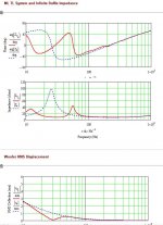
Is this reduced acoustic phase ripple the advantage of true Tqwt vs ML-TQWT, like mine? I can reduce mine with more stuffin, but not to the degree that you have achieved. OTOH, the impulse response from mine is very good, which i would think is an indicator of a quick cone response. Just trying to figure out what all these graphs mean. No where does MJK speak to these things.
Last edited:
all I can say is that , properly made long (folded) pyramidal MLTL (or derivation of it ) is much less boxy sounding than BR counterparts
difference is , if you put it that way - that BR is always haroomph-ing through pipe (opening ) while TL (derivatives ) are much less using those openings for relaxation
dunno - I'm telling you - trust to GM's words (even if I sometimes can't grasp sole simple sentence he's writing )
I'm just a tourist in those loudspeaker things
difference is , if you put it that way - that BR is always haroomph-ing through pipe (opening ) while TL (derivatives ) are much less using those openings for relaxation
dunno - I'm telling you - trust to GM's words (even if I sometimes can't grasp sole simple sentence he's writing
)I'm just a tourist in those loudspeaker things
Attachments

Last edited:
I was just playing with the program.
If there is a way to use square port, I would love to know.
Understood and I was just giving you something else to consider for maximizing SQ!
Square, rectangular ports of the same area are ~ identical to round until the aspect ratio exceeds ~1:1.2732, then friction losses begin increasing the length required for a given Fb with increasing ratio until around 1:9 when it heads towards aperiodic.
GM
all I can say is that , properly made long (folded) pyramidal MLTL (or derivation of it ) is much less boxy sounding than BR counterparts
difference is , if you put it that way - that BR is always haroomph-ing through pipe (opening ) while TL (derivatives ) are much less using those openings for relaxation
dunno - I'm telling you - trust to GM's words (even if I sometimes can't grasp sole simple sentence he's writing
I'm just a tourist in those loudspeaker things
They really need to brush that horses hair.
Understood and I was just giving you something else to consider for maximizing SQ!
Square, rectangular ports of the same area are ~ identical to round until the aspect ratio exceeds ~1:1.2732, then friction losses begin increasing the length required for a given Fb with increasing ratio until around 1:9 when it heads towards aperiodic.
GM
GM, What do you think of the enclosure 1.3 I modeled and how would your ideal enclosure differ. I have figured the port based simply on the area of the port diameter strecthed out into a rectangle, with the length being the thickness of the proposed baffle, about 1.25".
In detemining the rectangular port, is ther any difference if it stretches from one side to the other, like in Scottmoose' Pensil designs, or is it better to have it centered with a limit on width. Based on 1.4 design, a vent stretching across the 19" interior face would have to be 1.25" tall to equal the area of figured 2.75" port. I noticed in your big MLTL for the 416, the rectangular port was quite small.
Couple of questions.
How important is consistency of wavelets(?) of the first two impedance graphs?
How do you determine port tuning? I have been using WinIsd. I dont know how to model aperiodic tuning.
Here is try using better box ratio. Cant figure out why acoustic impedances are so ugly and why there is nasty port phase issue
I think it's important or I wouldn't have suggested you compare the different driver locations I posted plus I’ve posted that vents typically do well at 3rds, 5ths.
That said, stuffing density is the great equalizer, so for the vast majority of folks it’s not AFAIK and when there’s a large horn perched on top I typically ignore it somewhat since c-t-c spacing normally has a more audible impact on SQ.
At whatever frequency the cone excursion has the deepest null.
True aperiodic loading means to flatten the driver’s impedance peak as much as practical, so only a properly designed TL or BLH can do this AFAIK.
All others are semi-aperiodic at best and can be simmed in WinISD Pro by changing the rear chamber’s and vent’s Q values in the advanced tab, though the only way I know how to compare real Vs simmed is by impedance measurement.
In MJK’s software it would be increasing stuffing density throughout the line plus in the vent with best overall performance achieved when the right TL length Vs tuning is found.
GM
What is the major advantage of the reduced impedance peaks as seen in ZM's calculations included below?
My ignorant assumption is that it provides a more even load to the amp that should improve performance, but does this play out in real life as audible improvement?
This is a big deal when being driven by a high output impedance and why one must always tune to Fs for best overall performance/power transfer. With today's vanishingly low output impedance systems it only matters if the speaker's impedance drops below the amp's minimum rating.
There is group delay to consider though, so for higher Fs drivers it's best overall to tune them so that the lower impedance peak is damped.
Low Fs drivers tuned low have a higher group delay, but the vast majority of folks don't hear well enough down low, so by the time their hearing acuity improves, the group delay has decayed enough to be acoustically benign.
GM
Is this reduced acoustic phase ripple the advantage of true Tqwt vs ML-TQWT, like mine? I can reduce mine with more stuffin, but not to the degree that you have achieved. OTOH, the impulse response from mine is very good, which i would think is an indicator of a quick cone response. Just trying to figure out what all these graphs mean. No where does MJK speak to these things.
Correct, ideally we want a flat frequency and electrical phase response, but they are hard to come by except over a narrow BW.
Yes, ideally we want the system to be extremely well damped, so there would be ~nothing under the curve and no HF ripple [ringing]. Unfortunately, the only time I’ve witnessed it is from a small theoretically ideal BLH designed specifically to see if it was possible and otherwise useless except for a near-field app as it had virtually no power handling capability over most of its pass-band.
GM
difference is , if you put it that way - that BR is always haroomph-ing through pipe (opening ) while TL (derivatives ) are much less using those openings for relaxation
dunno - I'm telling you - trust to GM's words (even if I sometimes can't grasp sole simple sentence he's writing )
Right, look at a BR Vs TL impedance.
You can always ask for a clarification, though no guarantees I can explain it further as I don't understand a lot of the underlying math.
GM
GM, What do you think of the enclosure 1.3 I modeled and how would your ideal enclosure differ. I have figured the port based simply on the area of the port diameter strecthed out into a rectangle, with the length being the thickness of the proposed baffle, about 1.25".
In detemining the rectangular port, is ther any difference if it stretches from one side to the other, like in Scottmoose' Pensil designs, or is it better to have it centered with a limit on width. Based on 1.4 design, a vent stretching across the 19" interior face would have to be 1.25" tall to equal the area of figured 2.75" port. I noticed in your big MLTL for the 416, the rectangular port was quite small.
It’s just a reflex, so little can be done to improve it, though shifting the driver down to 19.43” might fine tune it a little. In room, the vent may need some ‘critical’ damping as most reflexes do IME.
Again, it’s all about width x height aspect ratio, so a narrow slot will lower tuning more than the sim predicts due to friction losses.
True, but it’s deep and it’s loading a MLTL tuned with an inverse tapered TQWT. These cabs date from ’69 when I only needed ~36 Hz tuning, so the vent was far larger and only ¾” deep, but as CDs, then DVDs, lowered the available LF I kept tuning it lower till now they’re around 15-16 Hz after ‘critical’ damping [the dense mesh screen visible behind the ¾” removable plate].
Since all this damping is combined with low tuning, the vent area can be smaller due to a lower vent mach even when pushed to hard with a 300 W/channel Mcintosh MC2300 or Altec 9444A/SA.
GM
- Home
- Loudspeakers
- Multi-Way
- Horn/TL combo