Hi,
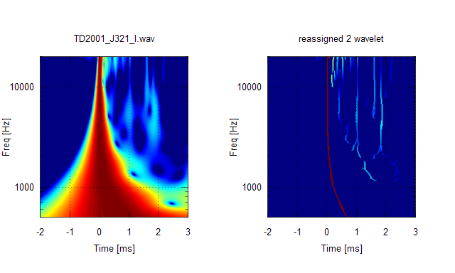
Yes the TD2001 produces better response.
Does it really take 1450$ driver that is specially matched with the horn to have signal that has the similar cleaniness than simple dome tweeter?! Because all the other horns/waveguides + drivers seen in this thread behave much worse than this.
- Elias
Yes the TD2001 produces better response.
Does it really take 1450$ driver that is specially matched with the horn to have signal that has the similar cleaniness than simple dome tweeter?! Because all the other horns/waveguides + drivers seen in this thread behave much worse than this.
- Elias
We can see that the J321 loading the TD2001 has a cleaner wavelet graph (that Jerzual horn built my friend Marco Hernry was specially designed to be used with the TAD TD2001).
Attachments

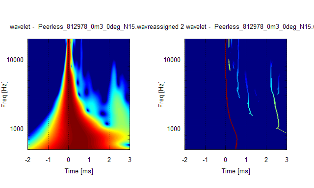
Let's see the tweeter diffraction some more.
Here 20€ Peerless dome tweeter was measured in a test baffle and some baffle edge diffraction is seen:
In order to remove the baffle edge diffractions from the above picture, let's hang the tweeter in free air by wires from the ceiling! Afterall, baffle-less hanging speakers have gained some popularity here recently Result is interesting: There's still diffractions The reassignment points strong diffraction at 0.2ms that comes from the front plate. Then more interesting is the diffractions numbered 1 to 4. They are diffractions caused by the wave travelling around the backside of the tweeter all the way to the front again multible times. If one calculates the around length from the tweeter's physical dimensions, it's about 0.55ms for one round.
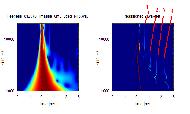
Clearly, hanging the element in the free air is not the ultimate solution either!
- Elias
Here 20€ Peerless dome tweeter was measured in a test baffle and some baffle edge diffraction is seen:
In order to remove the baffle edge diffractions from the above picture, let's hang the tweeter in free air by wires from the ceiling!
Afterall, baffle-less hanging speakers have gained some popularity here recently Result is interesting: There's still diffractions The reassignment points strong diffraction at 0.2ms that comes from the front plate. Then more interesting is the diffractions numbered 1 to 4. They are diffractions caused by the wave travelling around the backside of the tweeter all the way to the front again multible times. If one calculates the around length from the tweeter's physical dimensions, it's about 0.55ms for one round.
Clearly, hanging the element in the free air is not the ultimate solution either!
- Elias
Attachments

Last edited:
I'd suggest that properly filtered and equalized is better than normalization for comparison. It's artificial, otherwise, and not representative of actual use.To do fair comparison we have to look at the scaling - its pretty worthless to compare a 25dB and a 40dB plot - also its necessary to show normalized plots for a comparison that holds....
Every horn/driver is going to honk if driven near and/or below resonance and cutoff. The wavelet tells us how low we can actually drive it, which is also easily determined by listening to it while varying the highpass frequency. Filtered, the honk may be significantly mitigated. See #684.
I'm calling the trash above 10 kHz HOMs until proven otherwise. (Gotta get me some of Earl's magic foam.
)It's interesting to see a similar "knuckles and holes" pattern midband with both the TAD vs. XT1086. That's mouth/cab reflection, maybe. The pattern is quite regular, and the same as that of the strings after reassignment....

Last edited:
Hi, Scott,
Have you verified that it behaves as a lowpass filter in the VHF?
Several members have acquired foam per the spec that does not.
The differential attenuation is essential to it functioning according to Geddes's prescription; it must attenuate multiple passes more than the direct path.
Have you verified that it behaves as a lowpass filter in the VHF?
Several members have acquired foam per the spec that does not.
The differential attenuation is essential to it functioning according to Geddes's prescription; it must attenuate multiple passes more than the direct path.
Last edited:
- Elias[/QUOTE]
 A good one !
what a pity - LOL – the hunting can go on ....
Excellent wavelet analysis !
Of course - diffraction does not end at 360 deg included.
I already can see that we will have a loooot of fun with that new analysis “toy”
Michael
In order to remove the baffle edge diffractions from the above picture, let's hang the tweeter in free air by wires from the ceiling!
- Elias
A good one !Clearly, hanging the element in the free air is not the ultimate solution either!
- Elias
what a pity
- LOL – the hunting can go on ....Let's see the tweeter diffraction some more.
Here 20€ Peerless dome tweeter was measured in a test baffle and some baffle edge diffraction is seen:
In order to remove the baffle edge diffractions from the above picture, let's hang the tweeter in free air by wires from the ceiling!
...
The reassignment points strong diffraction at 0.2ms that comes from the front plate. Then more interesting is the diffractions numbered 1 to 4. They are diffractions caused by the wave travelling around the backside of the tweeter all the way to the front again multible times. If one calculates the around length from the tweeter's physical dimensions, it's about 0.55ms for one round.
- Elias
Excellent wavelet analysis !
Of course - diffraction does not end at 360 deg included.
I already can see that we will have a loooot of fun with that new analysis “toy”
Michael
I'd suggest that properly filtered and equalized is better than normalization for comparison. It's artificial, otherwise, and not representative of actual use.
Every horn/driver is going to honk if driven near and/or below resonance and cutoff. The wavelet tells us how low we can actually drive it, which is also easily determined by listening to it while varying the highpass frequency. Filtered, the honk may be significantly mitigated. See #684.
I’d say for a mid horn this might be ok *if* you already measure at flat EQ’ed FR – for anything else normalisation is the way to go *if* we are looking for fair / neutral comparison
Se below example – where you would not be able to get the point unless you examine / compare the normalized plots (upper right corner):
Once more - the same NEO3 tweeter - at horn contour and in open baffle configuration :
Open baffle :

120deg (included) honker :

Look at the NORMALISED plot to get the interesting difference,
Every horn/driver is going to honk if driven near and/or below resonance and cutoff. The wavelet tells us how low we can actually drive it, which is also easily determined by listening to it while varying the highpass frequency. Filtered, the honk may be significantly mitigated. See #684.
Not exactly IMO
As the topic of quarter wave honk was such a interesting topic up to now, other facets of horn honk still await “in depth” discussion
But anyway - I see any looped reflections part of horn honk – though I admit that the sonics associated with horn honk are more around the voice department.
Physically though – the top end reflections are nothing else – same quarter wave honk plus some “real” reflections at the phase plug parts...
For me its especially interesting that wavelet analysis is even accurate enough to show the veeeeeery early reflections occurring with planars.
One of the few drawbacks here is that the membrane isn’t radiating free, but - with the exception of ribbons - the wave has to pass through the magnet structure first.
Usually the magnet structure is in the range of ~ 1cm – very short time of travel indeed – but the multiple reflections can clearly be seen in my NEO 3 measurements .
Michael
Hello,
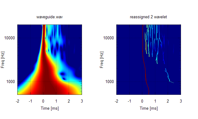
Looking at the geldee waveguide one can see that the problem is between the driver diaphragm and the horn throath. The very short time reflections/diffractions in order of 200us are not from the expansion part of the horn but the missmatch of driver and the throath. No foam can help here! You would need to stuff your foam inside the phase plug
I would say anything above 4kHz here is HOM
- Elias
Direct radiating drivers are always going to be cleaner than horns without foam inserts.
No, its not the question of „foam or not foam“ !
Foam - or any other dampening material - has only limited effect on reducing odd impact of looped reflections.
...
If we go back to "physics" understanding -
- the veeeery early reflections we see here in most horn plots are not from the "horn" but from the compression driver itself (diffraction at phase plug parts etc.) - being integral part of the horn contour of course, as noted several times - plus the reflections at point of compression driver / horn joint
I'm calling the trash above 10 kHz HOMs until proven otherwise. (Gotta get me some of Earl's magic foam.
The differential attenuation is essential to it functioning according to Geddes's prescription; it must attenuate multiple passes more than the direct path.
Attachments

Process my XT1086 only w/filter file for comparison. Same driver (DE250), presumably, different waveguide. (An allegedly crappy diffraction horn, actually.Looking at the geldee waveguide one can see that the problem is between the driver diaphragm and the horn throat.
)Earl never told us whether the foam was in place for those measurements, though I always presumed so. I believe he has suggested that to make it out of the waveguide, they are still reflecting laterally, and therefore mitigated, or at least attenuated, by the foam.I would say anything above 4kHz here is HOM
Others have challenged my supposition that HOMs begin at 10 kHz. I believe Earl has said that several times, but I haven't looked for citation(s). You need to make up your mind as to what is HOM and what is honk. I'm suggesting that midband reflections are neither....
Last edited:
Earl removes the screen from the B&C driver so it would be easy to stuff the driver's throat with foam as well. That would cover everything after the phase plug but it obviously wouldn't affect anything before the plug. I don't think Earl does that but it seems like it would be worth trying.Hello,
Looking at the geldee waveguide one can see that the problem is between the driver diaphragm and the horn throath. The very short time reflections/diffractions in order of 200us are not from the expansion part of the horn but the missmatch of driver and the throath. No foam can help here! You would need to stuff your foam inside the phase plug
Yikes! The stuff from foambymail is about $6/s.f. for 2". Dwk used it in his unities and liked it but I haven't seen any before after measurements.I have magic foam for experiments. 30ppi reticulated foam by 2 inches thick which could be shaped together in layers. Cost me around $20 per square foot. I can split it up for cost plus shipping.
Dryfast Foam, Outdoor Foams, Patio Furniture Custom Cushion Replacement, Hi-Flow Foam Scroll to speaker foam.
$8 per foot
Reticulated Foam Pads/Strips (P-G132-XX-ESPC)
32222.30 $32.22
Custom Width (inches): 12
Custom Length (inches): 48
.
https://www.h-oproducts.com/cart/pc/viewCategories.asp?pageStyle=l&idCategory=59
.
It would probably improve the XT1086 but is too dense for a horn as long as a big leCleac'h.
Sorry, I just double checked what I had and it is 1 inch 30ppi and was $8/ square foot plus shipping.Yikes! The stuff from foambymail is about $6/s.f. for 2". Dwk used it in his unities and liked it but I haven't seen any before after measurements.
Dryfast Foam, Outdoor Foams, Patio Furniture Custom Cushion Replacement, Hi-Flow Foam Scroll to speaker foam.
Reticulated Foam Pads/Strips (P-G132-XX-ESPC)
32222.30 $32.22
Custom Width (inches): 12
Custom Length (inches): 48
.
https://www.h-oproducts.com/cart/pc/viewCategories.asp?pageStyle=l&idCategory=59
.
It would probably improve the XT1086 but is too dense for a horn as long as a big leCleac'h.
I think you will have to show somthing in comparison rather than speculate.Hello,
Looking at the geldee waveguide one can see that the problem is between the driver diaphragm and the horn throath. The very short time reflections/diffractions in order of 200us are not from the expansion part of the horn but the missmatch of driver and the throath. No foam can help here! You would need to stuff your foam inside the phase plug
...
- Elias
The energy time curves shown in the attached pic differ only in lip shape after the lip reaches 180deg. It is not necessarily that high frequencies are effected only by the driver section.
Of course, measurement setup can also effect horn measurements. This is why it's necessary to look at both analysis/sim and real measurements.
Attachments

Last edited:
How then, in your opinion, the consecutive reflections/diffractions in order of 200us are formed unless in driver-throath interface?
- Elias
- Elias
I think you will have to show somthing in comparison rather than speculate.
The energy time curves shown in the attached pic differ only in lip shape after the lip reaches 180deg. It is not necessarily that high frequencies are effected only by the driver section.
Of course, measurement setup can also effect horn measurements. This is why it's necessary to look at both analysis/sim and real measurements.
I think it could be anything. In order to concluded whether those are created before or after the lip, one needs to do a series of measurements, some of which probably will be in the horn. If such is not possible, then it's necessary to explore the dimensions of the driver and the throat, and thw waveguide as well. For example, how much distance does 200usec compute too? How does it relate with the existing dimensions in the WG/driver?How then, in your opinion, the consecutive reflections/diffractions in order of 200us are formed unless in driver-throath interface?
- Elias
Last edited:
Yikes! The stuff from foambymail is about $6/s.f. for 2". Dwk used it in his unities and liked it but I haven't seen any before after measurements.
Dryfast Foam, Outdoor Foams, Patio Furniture Custom Cushion Replacement, Hi-Flow Foam Scroll to speaker foam.
Unfortunately, I don't have any measurements of any sort at the moment. The audio PC that was driving my U15's died a while ago taking my measurements and correction filters with it. Partly due to that and partly due to life intervening and demanding that my 'listening room' be overrun by storage requirements, I haven't actually run any sound through the U15's in well over a year.
I'm REALLY intrigued by all the activity surrounding wavelets though and would love to get some good measurements of the Unities for wavelet analysis - I think the multiple-entry topology would be very interesting to look at in terms of reflections back off the throat. With/without the foam would also be enlightening since things may be a bit more obvious than with conventional horns. Unfortunately it won't be happening any time soon - probably not until at least the fall.
Hello,
I just find this, highly relevant to the subject of Horn Honk LOL
Time-Frequency Analysis of Chanting Sanskrit Divine Sound “OM” Mantra
http://paper.ijcsns.org/07_book/200808/20080825.pdf
Since wavelets can be used to analyse "OM", there should not be a long way to get hold of "HOM" as well
- Elias
I just find this, highly relevant to the subject of Horn Honk LOL
Time-Frequency Analysis of Chanting Sanskrit Divine Sound “OM” Mantra
http://paper.ijcsns.org/07_book/200808/20080825.pdf
Since wavelets can be used to analyse "OM", there should not be a long way to get hold of "HOM" as well
- Elias
Since wavelets can be used to analyse "OM", there should not be a long way to get hold of "HOM" as well
- Elias
OM & HOM - same mantra technique - kind of "looped reflections" from a certain point of view - LOL - great find...
Michael


- Status
- This old topic is closed. If you want to reopen this topic, contact a moderator using the "Report Post" button.
- Home
- Loudspeakers
- Multi-Way
- Horn Honk $$ WANTED $$