Re: The "Sound"
Yes indeed!! That is a very big problem. You would need 8 lines on the screen for all the harmonics, and 8 more for the phase. A real mess. And then what happens if you want to compare 2 measurements?
Perhaps a drop down menu with radio buttons to turn on or off each harmonic would work. Phase could still be turned on or off with the existing button. Then somehow you have to identify each harmonic's line. Color? Dots and dashes? Line markers? I don't know.
Will do some more DCX measurements soon.
askbojesen said:My problem is how to visualize this in a consistent way so the plot is not overcrowded by curves.
Yes indeed!! That is a very big problem. You would need 8 lines on the screen for all the harmonics, and 8 more for the phase. A real mess. And then what happens if you want to compare 2 measurements?
Perhaps a drop down menu with radio buttons to turn on or off each harmonic would work. Phase could still be turned on or off with the existing button. Then somehow you have to identify each harmonic's line. Color? Dots and dashes? Line markers? I don't know.
Will do some more DCX measurements soon.
You could show them "grayed out" and then when you mouse over it highlights the harmonic, color coding the harmonic and phase of the other three measurements and shows additional info in another area.
Or you mouse over somewhere else and have the same happen.
I like the "mouse over and highlight with things happening" approach as showing the information the user wants becomes instantly available instead of clicking a million radio buttons.
As I doubt any one would want to compare second harmonic on one driver with third on another. Although leaving the option would be nice.
UI design is interesting but very hard to get right. You have done excellent this far so it should work out great I think.
How about adding additional tabs that shows more types of information.
Tabs are very easy to work with and can quickly show massive amounts of information while leaving the "basic" tab easy to understand and use (just don't layer them on top of each other).
That way you can have an "expert mode" with experimental features and "hard to understand" stuff.
You could really expand things with signal processing and infinite loop processing without making things uncomfortable for the casual user.
But it would then rival the "pay a lot" programs and who knows what happens then.
If you could find a way to rival this kind of CSD processing...
http://www.wavecapture.com/RoomCapture.html
Finally got a chance to mess around with this a little bit. Great stuff!
A few things I would like to see (maybe I just haven't found the feature yet). I have needed a simple computer based RTA for tweaking and programing in real time while seeing how it effects the frequency response and phase.
For instance I could set up an approximate stacked filter with variable controls and fine tune the filter points in real time while seeing the effects of my tweaks. Maybe I am just not looking hard enough but the best one I could find for RTA only showed me -30dB down and had no phase information.
So for precise measurements currently I am forced to get into this loop of opening host>rendering test file through filters>analyse file>re-render clean test tone(repeat). It would be much simpler on my end to be able to stream a test sound constantly while I tweak my programs in real time.
Re: Feature request
The most interesting technique that I have ever seen in this regard is where the impulse response is "extended" past the window (required by gating the reflections) and thus extending the LF response. This is done by using the Thiel Small parameters from another set of measurements and using this data to interpolate the decaying impulse response corresponding to the impulse within the window and the know characteristics from the T-S parameters. LAUD did this and it worked quite well. There are several methods out there, I don't know which one works best.
soongsc said:If there is any possible way to measure low frequency without room effects, that would be very much appreciated.
The most interesting technique that I have ever seen in this regard is where the impulse response is "extended" past the window (required by gating the reflections) and thus extending the LF response. This is done by using the Thiel Small parameters from another set of measurements and using this data to interpolate the decaying impulse response corresponding to the impulse within the window and the know characteristics from the T-S parameters. LAUD did this and it worked quite well. There are several methods out there, I don't know which one works best.
Re: Calibration using a pistonphone
I was somewhat short on my suggestion, the idea was something more "automatic", you enter the level the calibrator gives (usually 94dB or 104dB) and the software do all the trick automatically to give you proper absolute readings. So everything in the chain would be taken into account (mic sens, preamp gain, soundcard gain...)
But as it is I would like to take this opportunity to thank you for this amazing piece of work and ... for free
Best regards from Paris
Jean-Claude
askbojesen said:
Then how is this one frequency sensitivity measured?
I could of course make a bandpassed levelmeter to make this calibration
good idea!
I was somewhat short on my suggestion, the idea was something more "automatic", you enter the level the calibrator gives (usually 94dB or 104dB) and the software do all the trick automatically to give you proper absolute readings. So everything in the chain would be taken into account (mic sens, preamp gain, soundcard gain...)
But as it is I would like to take this opportunity to thank you for this amazing piece of work and ... for free
Best regards from Paris
Jean-Claude
soongsc said:For pure drivers, it works fine for SPL, but I was wondering about systems measurements. Especially vented enclosures.
I don't see the difference, the technique would work for any source or full system. If the box is ported then you need to know some more parameters thats all.
I would expect it to be tricky. I wonder whether the changed impulse would show CSD difference between a sealed vs vented design.gedlee said:
I don't see the difference, the technique would work for any source or full system. If the box is ported then you need to know some more parameters thats all.
My LF-Dilemma
I'm a physicist of education and it hurts my ideology to guess the response. It can be a reasonable method, but we must distinguish measurements from extrapolations - I mean use the correct nomenclatures. A measurement vs. an extrapolation
I have very good experience making near field (1-5 cm) from LF drivers.
I'm struggling to make time+gain alignment between the LF and the MF (Bass -> Mid with x-over at 100-150 Hz).
My experience here is that we can not and will not neglect the room for LF measurements and alignments. Remember the wavelength at 86 Hz is 4 meters.
We all know that we cannot measure the far field LF without the room. The best we could do is measure at different positions and in different rooms, then we know that the difference is the room.
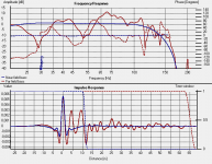
Far field LF measuring is really hard. In HOLM Acoustics we are correcting bass drivers near field using FIR-filters. Attachment shows a corrected bass near field and far field.
I'm really in a LF dilemma. My speaker sounds awful outside in the garden were there is no room, but in my room the impulse response is so ugly
gedlee said:The most interesting technique that I have ever seen in this regard is where the impulse response is "extended" past the window (required by gating the reflections) and thus extending the LF response. This is done by using the Thiel Small parameters from another set of measurements and using this data to interpolate the decaying impulse response corresponding to the impulse within the window and the know characteristics from the T-S parameters. LAUD did this and it worked quite well. There are several methods out there, I don't know which one works best.
I'm a physicist of education and it hurts my ideology to guess the response. It can be a reasonable method, but we must distinguish measurements from extrapolations - I mean use the correct nomenclatures. A measurement vs. an extrapolation
I have very good experience making near field (1-5 cm) from LF drivers.
I'm struggling to make time+gain alignment between the LF and the MF (Bass -> Mid with x-over at 100-150 Hz).
My experience here is that we can not and will not neglect the room for LF measurements and alignments. Remember the wavelength at 86 Hz is 4 meters.
We all know that we cannot measure the far field LF without the room. The best we could do is measure at different positions and in different rooms, then we know that the difference is the room.
Far field LF measuring is really hard. In HOLM Acoustics we are correcting bass drivers near field using FIR-filters. Attachment shows a corrected bass near field and far field.
I'm really in a LF dilemma. My speaker sounds awful outside in the garden were there is no room, but in my room the impulse response is so ugly
Attachments
Re: My LF-Dilemma
I don;t see why not.
I'm a physicist too and I have no problem with "extrapolation" of missing data from known data. It's done all the time in cosmology and almost every area of physics that I know. You must, of course, distinguish between the actual data and the extrapolated data and physicists usually put error bounds on these extrapolations, which, of course, get greater the longer the tail, but then the tail is getting smaller and smaller. It has been shown that these "extrapolations" can be very accurate.
As to the room and the source coupling and the use of near field data to EQ the source, I could go on and on (and would love to since this is what I did my PhD on "LF sound field in small rooms" and I have spent decades on the topic), but that would easily go far astray of this threads topic, and I think that what you have done here is important. Should you care to continue with the LF discussion sometime just let me know - I'd be happy to attend.
soongsc said:
I would expect it to be tricky. I wonder whether the changed impulse would show CSD difference between a sealed vs vented design.
I don;t see why not.
askbojesen said:
I'm a physicist of education and it hurts my ideology to guess the response. It can be a reasonable method, but we must distinguish measurements from extrapolations - I mean use the correct nomenclatures. A measurement vs. an extrapolation
I'm a physicist too and I have no problem with "extrapolation" of missing data from known data. It's done all the time in cosmology and almost every area of physics that I know. You must, of course, distinguish between the actual data and the extrapolated data and physicists usually put error bounds on these extrapolations, which, of course, get greater the longer the tail, but then the tail is getting smaller and smaller. It has been shown that these "extrapolations" can be very accurate.
As to the room and the source coupling and the use of near field data to EQ the source, I could go on and on (and would love to since this is what I did my PhD on "LF sound field in small rooms" and I have spent decades on the topic), but that would easily go far astray of this threads topic, and I think that what you have done here is important. Should you care to continue with the LF discussion sometime just let me know - I'd be happy to attend.
New Release: Saving wave files
New Release:
What's New
http://www.holmacoustics.com/downloads/HOLMImpulse/ChangeLog.txt
Version 1.1.6.2 (2009-06-22)
Features/Changes:
* Save impulse response as 16/24 bit wave file. (for ARTA import)
* Save measurement signal as wave file.
* Save inverse signal as normalized wave file.
* Save output and recording as wave file (Optional)
Bugfixes:
* Signal is allways LogSweep
What's next
http://www.holmacoustics.com/downloads/HOLMImpulse/Issues.txt
What to do with these wavefiles?
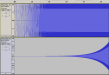
I actually think it's interesting to see the waveform of the inverse correlation - maybe fadein would give a nicer inverse correlatin of the logsweep. Farina and his friends does not seem to care about the inverse waveform, but that might be why they could not explain their low-frequent artifacts.
Attached logsweep and the inverse
New Release:
What's New
http://www.holmacoustics.com/downloads/HOLMImpulse/ChangeLog.txt
Version 1.1.6.2 (2009-06-22)
Features/Changes:
* Save impulse response as 16/24 bit wave file. (for ARTA import)
* Save measurement signal as wave file.
* Save inverse signal as normalized wave file.
* Save output and recording as wave file (Optional)
Bugfixes:
* Signal is allways LogSweep
What's next
http://www.holmacoustics.com/downloads/HOLMImpulse/Issues.txt
What to do with these wavefiles?
I actually think it's interesting to see the waveform of the inverse correlation - maybe fadein would give a nicer inverse correlatin of the logsweep. Farina and his friends does not seem to care about the inverse waveform, but that might be why they could not explain their low-frequent artifacts.
Attached logsweep and the inverse
Attachments
Re: My LF-Dilemma
I was wondering whether it makes sense to sort of filter part of impulse outside the window. The rationale for this is that whever you have reflection, there would be increase rate of change in the impulse because combination of original wave and reflective wave introduces a result with higher order frequency content. Perhaps if we use a fixed or variable rate limiter on the impulse, it might be possible to reduce the room effects to a usable degree?askbojesen said:
I'm a physicist of education and it hurts my ideology to guess the response. It can be a reasonable method, but we must distinguish measurements from extrapolations - I mean use the correct nomenclatures. A measurement vs. an extrapolation
I have very good experience making near field (1-5 cm) from LF drivers.
I'm struggling to make time+gain alignment between the LF and the MF (Bass -> Mid with x-over at 100-150 Hz).
My experience here is that we can not and will not neglect the room for LF measurements and alignments. Remember the wavelength at 86 Hz is 4 meters.
We all know that we cannot measure the far field LF without the room. The best we could do is measure at different positions and in different rooms, then we know that the difference is the room.
Far field LF measuring is really hard. In HOLM Acoustics we are correcting bass drivers near field using FIR-filters. Attachment shows a corrected bass near field and far field.
I'm really in a LF dilemma. My speaker sounds awful outside in the garden were there is no room, but in my room the impulse response is so ugly
Hi Ask,
At first, again big thanks for your rapid update and the new features, very good!
The inverse imports correctly (32Bit-float, that is what I've tested), but the stimulus doesn't (see attachment). Looks like a header problem.
Samplitude lets me nevertheless save into an new file, and then the sample lengths of both files match (1048576, =2^20).
But both files look funny. The stimulus has something odd at the very end (maybe a result of the above problem), and no raised-cosine fade-in/out (like Acourate's LogSweepRecorder does). The inverse starts with an exp "fade-out" of fs/2 samples leading into sort of a "DC tail" and there is this fs/2 noise on the signal in the beginning part of the wave.
So much for today (tonight that is, uh, it's 3:30AM)... I'll dig deeper tomorrow.
- Klaus
Attachments
fake measurements
This is not measurement. It is simulation. The simulation of the LF response from the Thiele/Small parameters. The latter is well known, but it hasn't been called measurement or "interpolation" yet. To do such is well known in physics, but it is not called measurement.
It isn't to difficult to take a model as the Thiele/Small parameters and simuate, adjust the level at a certain point and draw the curves to extrapolate. But it is - if the result should be considered as measurement - fake. It gives pretty pictures that show what You might want to see, or to show lets say to customers.
The truth is, the room alters the bass response that much, a plain curve is wrong in any case. That isn't cured by extrapolating from a rough low level model at one single point. A designer keen for quality would stand the problem despite of its complexity. And that is done using real measurements especially if they show what kind of mess is to be dealt with.
As far as cosmology is concerned in a later post by gedlee such "interpolation" and extrapolation is surely common. But that is science, hypothesis, speculation about things that are 12 billion years gone and/or 12 billion years X speed of light away. About forces that MADE the whole universe. Who compares such science with a basic specification of audio gear? You don't need a spec to live in the universe, but You should be sure that in a spec of a speaker true measurement is kept apart from lumped circuit simulation.
gedlee said:
The most interesting technique that I have ever seen in this regard is where the impulse response is "extended" past the window (required by gating the reflections) and thus extending the LF response. This is done by using the Thiel Small parameters from another set of measurements and using this data to interpolate the decaying impulse response corresponding to the impulse within the window and the know characteristics from the T-S parameters. LAUD did this and it worked quite well. There are several methods out there, I don't know which one works best.
This is not measurement. It is simulation. The simulation of the LF response from the Thiele/Small parameters. The latter is well known, but it hasn't been called measurement or "interpolation" yet. To do such is well known in physics, but it is not called measurement.
It isn't to difficult to take a model as the Thiele/Small parameters and simuate, adjust the level at a certain point and draw the curves to extrapolate. But it is - if the result should be considered as measurement - fake. It gives pretty pictures that show what You might want to see, or to show lets say to customers.
The truth is, the room alters the bass response that much, a plain curve is wrong in any case. That isn't cured by extrapolating from a rough low level model at one single point. A designer keen for quality would stand the problem despite of its complexity. And that is done using real measurements especially if they show what kind of mess is to be dealt with.
As far as cosmology is concerned in a later post by gedlee such "interpolation" and extrapolation is surely common. But that is science, hypothesis, speculation about things that are 12 billion years gone and/or 12 billion years X speed of light away. About forces that MADE the whole universe. Who compares such science with a basic specification of audio gear? You don't need a spec to live in the universe, but You should be sure that in a spec of a speaker true measurement is kept apart from lumped circuit simulation.
I recall that Dr. John Kreskovsky described a method of measuring the low frequency response of a loudspeaker in a reverberant environment as can be seen here http://www.musicanddesign.com/Matched_Filters.html
But it may not be the easiest method for a diy guy with only a limited understanding of the technique.
Peter
But it may not be the easiest method for a diy guy with only a limited understanding of the technique.
Peter
PLB said:I recall that Dr. John Kreskovsky described a method of measuring the low frequency response of a loudspeaker in a reverberant environment as can be seen here http://www.musicanddesign.com/Matched_Filters.html
But it may not be the easiest method for a diy guy with only a limited understanding of the technique.
Peter
Same applies to John. No measurement, shows exactly nothing else than any rough simulation. Some people look at it as if it was a measurement. Some people expect measured data that has been developed and compiled by some artful "magic" deep within the computing mashine. Alas, that very hope is void.
One possibility for LF performance is parametric analysis of the impulse response to separate the resonant contributions of the room from the underlying response, however it is difficult to distinguish intentional resonances (e.g. port) from a modal effect. Information content problems (number of samples in the response that can be reliably analysed) as modal density increases restrict that analysis to the bottom 100Hz or so.
- Home
- Design & Build
- Software Tools
- HOLMImpulse: Measuring Frequency & Impulse Response