I've been working at replacing caps & resistors after a channel went out in (another) Harmon Kardon A500. Prior to me changing out components, it was working (albeit sounded dark and muddy like stuff needed to be replaced). In the process, I removed some things like the low and high cuts, contour, and the "ambiance" channel. Long story short, after replacing all the caps and resistors I've got some REALLY bad hum going on. I'm on a simple path, using the "aux" input to bypass the phono stage so I'm trying to chase down where exactly I'm getting this hum.
This one had some work done by the P/O before I got it. In addition to replacing (and adding) some caps; all of the internal signal wires had the shield wire soldered to ground on both ends. I lifted one end, thinking that these were all ground loops. Was I wrong in doing this and do I now have a bunch of little antenna?
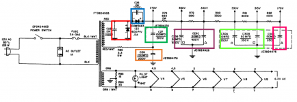
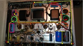
That aside, I started looking at the power section of this amp and was really confused with a few of the choices made....well one in particular. Attached is a shot of the guts, along with the power section of the scheme:
A - GND connection to buss-bar from orange cap (C28)
B - GND connection to OPT speaker (-) from orange cap (C28)
C - GND connection to Purple cap (C29) from Orange cap (C29)
D - GND connection from buss-bar to light-Green cap (C30-A/B)
-Pink cap is C30-C
E - Rectifiers from PT output. Red is the cap+diode to ground (on C28), blue is cap+diode to power (R78).
F - Additional 470u cap; from the "370V" point, x4 22ohm dale resistors in paralle (5.5 ohm) connect to
this capacitor which then goes to ground. Power goes to the output tube screens.
G - Additional 470u cap; After R78 to ground, this would be in parallel with C29-B.
H - "350V" power from R78/screens to purple cap (C29).
Sans the extra caps and the addition of the huge wirewound resistors for the screen voltage tap, everything else appears to be as-built. The choice to run the ground from the light-green cap (C30-A/B) to the buss-bar really perplexes me. I would have thought the better connection for that would be to point-C (C29's GND from the other side of the amp). As it is now, having the ground connection on that side of the buss-bar, isn't there noise being injected into the amplification stage? Curious if this is causing the noise, or am I overthinking and it's nothing to worry about?
Re-cleaned all my solder joints and re-soldered them to make sure I didn't have a cold joint somewhere. Anywhere else I should be looking for noise issues? Borked wiring paths? Possible I screwed something up when I removed the "features" ?
This one had some work done by the P/O before I got it. In addition to replacing (and adding) some caps; all of the internal signal wires had the shield wire soldered to ground on both ends. I lifted one end, thinking that these were all ground loops. Was I wrong in doing this and do I now have a bunch of little antenna?
That aside, I started looking at the power section of this amp and was really confused with a few of the choices made....well one in particular. Attached is a shot of the guts, along with the power section of the scheme:
A - GND connection to buss-bar from orange cap (C28)
B - GND connection to OPT speaker (-) from orange cap (C28)
C - GND connection to Purple cap (C29) from Orange cap (C29)
D - GND connection from buss-bar to light-Green cap (C30-A/B)
-Pink cap is C30-C
E - Rectifiers from PT output. Red is the cap+diode to ground (on C28), blue is cap+diode to power (R78).
F - Additional 470u cap; from the "370V" point, x4 22ohm dale resistors in paralle (5.5 ohm) connect to
this capacitor which then goes to ground. Power goes to the output tube screens.
G - Additional 470u cap; After R78 to ground, this would be in parallel with C29-B.
H - "350V" power from R78/screens to purple cap (C29).
Sans the extra caps and the addition of the huge wirewound resistors for the screen voltage tap, everything else appears to be as-built. The choice to run the ground from the light-green cap (C30-A/B) to the buss-bar really perplexes me. I would have thought the better connection for that would be to point-C (C29's GND from the other side of the amp). As it is now, having the ground connection on that side of the buss-bar, isn't there noise being injected into the amplification stage? Curious if this is causing the noise, or am I overthinking and it's nothing to worry about?
Re-cleaned all my solder joints and re-soldered them to make sure I didn't have a cold joint somewhere. Anywhere else I should be looking for noise issues? Borked wiring paths? Possible I screwed something up when I removed the "features" ?
Attachments
Does this amp have similar circuitry to the HK A300?
If so, it may have a split load inverter.
I had a tube in the A300 inverter that had filament to cathode leakage, and there was
hum, especially the higher frequency products of hum, i.e. sounded like drill motor noise.
Put a 0.1 capacitor from the grid of that inverter to ground, and see if the 'hum' goes away, or reduces significantly, then the inverter is not the cause of the problem.
In either case, remove the cap when you get done testing.
If the inverter is the cause, replace the inverter tube (hopefully one with low filament to cathode leakage).
Does this amp have similar circuitry to the HK A300?
If so, it may have a split load inverter.
I had a tube in the A300 inverter that had filament to cathode leakage, and there was
hum, especially the higher frequency products of hum, i.e. sounded like drill motor noise.
Put a 0.1 capacitor from the grid of that inverter to ground, and see if the 'hum' goes away, or reduces significantly, then the inverter is not the cause of the problem.
In either case, remove the cap when you get done testing.
If the inverter is the cause, replace the inverter tube (hopefully one with low filament to cathode leakage).
Correct, they are a near identical design and the A500 uses a variation of a split-load PI. I had tried swapping out the PI tube with another 12AU7 I had but I've only got just the one extra AU, so it's possible that both are bad. I'll try coupling the signal to ground though and see what happens. I was also planning on moving the other power cap ground as a test and see what happens.
Try using the correct value capacitors. Unless of course, you know more than the designers.
No need to be snide guy, did you totally miss the part where I said someone else did all the capacitor additions and changes? I'm in there to (hopefully) remedy the dead channel and despite the "wrong values" everything else was working fine. As expected the rail voltages are elevated slightly from the addition of the caps but it doesn't appear to be anything outside the realm of reasonable.
I doubt the ground configuration you described is the cause of the bad hum. (it may be partially the cause). What is important is that the anode of the power supply diode that is connected to ground and the negative lead of C28 are connected to the same point, and then that point can be connected to the ground bus on the noisy side. There is quite a bit of ripple current there between those two ground connections, so putting them at the same point will eliminate ripple current flowing through the chassis or through other ground circuitry.
It's been years since I was inside my A500, and I don't have the schematic in front of me, but by way of information I do remember that the split load inverter provides some positive feedback to the first voltage gain stage of the power amp section. I can't remember if those two stages are direct or AC coupled though.
See if the hum goes away if you ground the grid of the voltage gain stage of the power amp. If it does, then the hum is either a) related to how that grid receives its ground reference, or b) being introduced from a previous stage. In any event that will at least tell you if the hum is coming from the preamp stages or the power amp stage.
Also, probably obvious, but make sure the filament circuits have a proper ground reference. That could cause a lot of hum if that ground reference is wrong or missing. Also, just a note (not your issue as you've described but informational), be aware that the first three tubes (phono section and first tube in preamp section) get their filament voltage from the cathode voltage of the output stage. They did that probably as a cost-saving move.
The HK A300 had DC filaments (they were the bias resistor for the 4 output tube cathodes that were in parallel).
I think that this was the inexpensive way to make the phono stage, and first line level tubes not to have any hum from AC filaments and the proximity of AC wiring near these tubes.
I contemplated wiring the phase splitter tube filaments in series with those other tubes, and then returning the output tube grid resistors to the first tube filament (at + 12V). The bias would have been roughly the same, but a little less, there would be reduced output tube current, and so reduced filament current because of the Plate to Cathode voltage that was reduced by 12V.
I doubt the ground configuration you described is the cause of the bad hum. (it may be partially the cause). What is important is that the anode of the power supply diode that is connected to ground and the negative lead of C28 are connected to the same point, and then that point can be connected to the ground bus on the noisy side. There is quite a bit of ripple current there between those two ground connections, so putting them at the same point will eliminate ripple current flowing through the chassis or through other ground circuitry.
That's the thought i had as well, I was just thinking MOST of the ripple occurs in the power supply/filter so it was a "maybe" that I wanted to look at. *shame on me* i don't have a scope to look at it with and outside of the basic re-cap that I've done on 1-2 others I've not pushed real hard into this chassis. Was hoping someone could chime in with some "grey hair" experience, so thank you for the heads up!
that was kind of the thought i had too after talking about coupling to ground at the PI. Work my way back and see if I couldn't isolate *where* in the stage i was injecting noise. This is definitely on my list of "todos"....See if the hum goes away if you ground the grid of the voltage gain stage of the power amp. If it does, then the hum is either a) related to how that grid receives its ground reference, or b) being introduced from a previous stage. In any event that will at least tell you if the hum is coming from the preamp stages or the power amp stage.
Also, probably obvious, but make sure the filament circuits have a proper ground reference. That could cause a lot of hum if that ground reference is wrong or missing. Also, just a note (not your issue as you've described but informational), be aware that the first three tubes (phono section and first tube in preamp section) get their filament voltage from the cathode voltage of the output stage. They did that probably as a cost-saving move.
The HK A300 had DC filaments (they were the bias resistor for the 4 output tube cathodes that were in parallel).
I think that this was the inexpensive way to make the phono stage, and first line level tubes not to have any hum from AC filaments and the proximity of AC wiring near these tubes.
Both of you are exactly right that it was done as a cost-savings measure (from everything I've been able to research on it anyway). There's a couple other "features" in the A300/500 that were done this way and are very common "re-wires" in the chassis. I wanted to try and re-cap, eliminate and simplify things a bit before going that far into it but redoing the power supply, adding a xfmr for the filament and simplifying the circuitry are on the horizon. This chassis is one I've had on the bench for a while and have also been doing some calcs/re-design on. The hope was to use my current state as a stepping stone to greater things. (gotta get it working first though!)
That was another one of the options I had considered as an alternative to adding a standalone LV xfmr for the filaments. As I mentioned earlier though, I wanted to try and get everything working as-is with a relatively "stock" topology before going in much deeper. I've got one other A500 that's working swimingly after a simple re-cap and since this one already had some meddling hands, I thought it would be a prime candidate for some experimental re-wiring.I contemplated wiring the phase splitter tube filaments in series with those other tubes, and then returning the output tube grid resistors to the first tube filament (at + 12V). The bias would have been roughly the same, but a little less, there would be reduced output tube current, and so reduced filament current because of the Plate to Cathode voltage that was reduced by 12V.
Last edited:
- Status
- This old topic is closed. If you want to reopen this topic, contact a moderator using the "Report Post" button.
- Home
- Amplifiers
- Tubes / Valves
- HK A500 rebuild issues