I have purchased from his eBay store. Are you referring to his mute circuit PCB when you say “switch circuit”? I’m not trying to be pushy, I am genuinely curious about the PCBs you are using. For instance, the Elliot Sounds bleeder circuit; is that something you DIY’d or is that a project he offers (yes, I looked)?Pete has an Ebay store: https://www.ebay.com/str/pmillett
@Binkman It's the AC Delay circuit http://www.pmillett.com/acdly.html
Other than the Millet circuit, everything is DIY, I spun the PCB's.
Other than the Millet circuit, everything is DIY, I spun the PCB's.
Hi, I also used one of these transformers. At the time there was a note saying to use a 47k loading resistor eg r1.Can I calculate the value of R1?
Tube resistance = 65R
Source resistance of the transformed cartridge = 500R (5Rx100) Ortofon MC Quintet Black S x Sowter 1480
Transformer secondary resistance = 60R
Grid stops = 100R
Total resistance = 725R
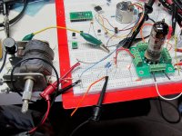
However, I hooked up a signal generator and scope with the setup suggested in the artical and devised (largely through experimentation) a zobel network to try and get the best square response and Max signal transfer out of a benz Wood sl.
There is an excellent artical at http://www.rothwellaudioproducts.co.uk/html/mc_step-up_transformers_explai.html
Which you should read.
Also unsure why you have just added up those resistances?
Anyway, if unsure, stick with the 6k8 as stock and then try a 47k in r1.
If you don't have a scope and thoroughly understand the testing setup, don't bother as you may damage the transformer putting too much current through it.
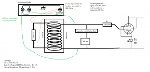
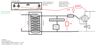
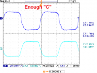
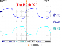
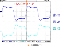
Not exactly...you need a small square wave of 1kHz or 10kHz from the function generator. 1mV is OK. The scope probe should be coupled to the anode of the D3A with a capacitor -- 100nF, 220nF, 470nF and the RIAA comp network NOT connected.Is this the right way to perform the measurement? See attachment.
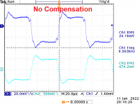
The point of compensation is to get a square wave which is not overly-damped. The compensation network RC, offsets the leakage inductance and interwinding capacitance of the transformer secondary. Some companies give you these stats, but a guess is ~70mH leakage inductance for a Cinemag transformer.
Attachments
Thanks jackinnj, I just have a few more questions, hope it's okay? I'm a newbieNot exactly...you need a small square wave of 1kHz or 10kHz from the function generator. 1mV is OK. The scope probe should be coupled to the anode of the D3A with a capacitor -- 100nF, 220nF, 470nF and the RIAA comp network NOT connected.
The point of compensation is to get a square wave which is not overly-damped. The compensation network RC, offsets the leakage inductance and interwinding capacitance of the transformer secondary. Some companies give you these stats, but a guess is ~70mH leakage inductance for a Cinemag transformer.
")
1. How do you get 5 ohm source impedance if you have removed the 5 ohm resistor on primary winding?
2. "The scope probe should be coupled to the anode of the D3A with a capacitor - 100nF, 220nF, 470nF and the RIAA comp network NOT connected." Can you explain why I have to measure on the anode, and is there not high voltage on this side? and what is the reason for using a 220nF capacitor and a 470k resistor on the scope probe?
3. Why does the RIAA comp network NOT need to be connected?
1) Not going to affect the ringing of the transformer, since this issue arises from the leakage inductance and interwinding capacitance of the secondary.Thanks jackinnj, I just have a few more questions, hope it's okay? I'm a newbie
1. How do you get 5 ohm source impedance if you have removed the 5 ohm resistor on primary winding?
2. "The scope probe should be coupled to the anode of the D3A with a capacitor - 100nF, 220nF, 470nF and the RIAA comp network NOT connected." Can you explain why I have to measure on the anode, and is there not high voltage on this side? and what is the reason for using a 220nF capacitor and a 470k resistor on the scope probe?
3. Why does the RIAA comp network NOT need to be connected?
2) You can measure it at the grid of the amplifying tube, but you are loading it a bit with the impedance of the scope probes. The capacitor and 470K resistor on the output of the tube allow you to measure at the juncture of the res and cap and it is a much larger signal.
3) You want to measure the ringing of the transformer by itself.
Hi everyone...
I have a question about the sym. filament supply.
The ECC88 and the D3a as well needed a filament voltage of 6,3V. There is no possibility of series heating with 12,6 V supply , only 6,3 V
I read the schematic below in that way, that the filament of each single tube ECC88 or D3a is driven with +6,3V to Ground
and the other ECC88 or D3a ( left Ch. or 2nd Stage ) is driven with -6,3V to Ground.
am i right ?? Thank you.
I read the schematic below in that way, that the filament of each single tube ECC88 or D3a is driven with +6,3V to Ground
and the other ECC88 or D3a ( left Ch. or 2nd Stage ) is driven with -6,3V to Ground. Am I right ?? Thank you.
Yes, you are understanding it correctly.
The ECC88 and the D3a as well needed a filament voltage of 6,3V. There is no possibility of series heating with 12,6 V supply , only 6,3 V
Well… this IS two 6.3V supply in series to make a 12.6V supply. We just happen to call the center node “ground”.
ok thank you.Yes, you are understanding it correctly.
Well… this IS two 6.3V supply in series to make a 12.6V supply. We just happen to call the center node “ground”.
Are there any preferences for the Tubes witch filament pin to + or - an witch to the "GND" ?
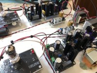
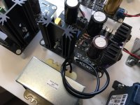
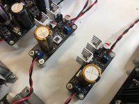
This is by far the best phono stage I ever built.
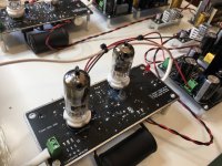
Here is my implementation using Zeno regulators for high voltage and filament. Noise is far below any other tube phono I have and I had lot of them.
Tube used: Siemens D3A and JJ E88CC gold.
Here is my implementation using Zeno regulators for high voltage and filament. Noise is far below any other tube phono I have and I had lot of them.
Tube used: Siemens D3A and JJ E88CC gold.
Attachments
- Home
- General Interest
- diyAudio.com Articles
- His Master's Noise: A Thoroughly Modern Tube Phono Preamp