
I am using 2 transformers since the filament supplies are regulated per SY's original design. You might get lucky and find a surplus trafo as he did. The B+ supply including regulators is going to take ~80mA. It's a bit of a piggy with the first stage drawing 20mA each.
Good source for B+ transformers are beater test equipment from Eico, Allied and Heath.
Good source for B+ transformers are beater test equipment from Eico, Allied and Heath.
Yes, i was intending on using 2 transformers. I was wondering if unused extra windings had any detrimental effects.
Anyway, been looking around and ive got curious as to why the design calls for a centre tap. Im guessing that valve amplifers have traditionally used that design due to valve rectifiers. Once silicon diodes came then Im guessing there was a general shift to bridge rectifiers and then cheaper (?) transformers could be used.
Ive found a 275v single output transformer at 180mA (no centre tap or anything). Are there any reasons why i shouldnt use this with a suitably rated bridge rectifier at the front end of the psu instead of the more traditional arrangement. The article implies that the slightly higher voltage should be beneficial.
Finding "just the right " transformer seems to be a bit harder or very costly in the uk.
Jackinnj, I think we may be at cross purposes.
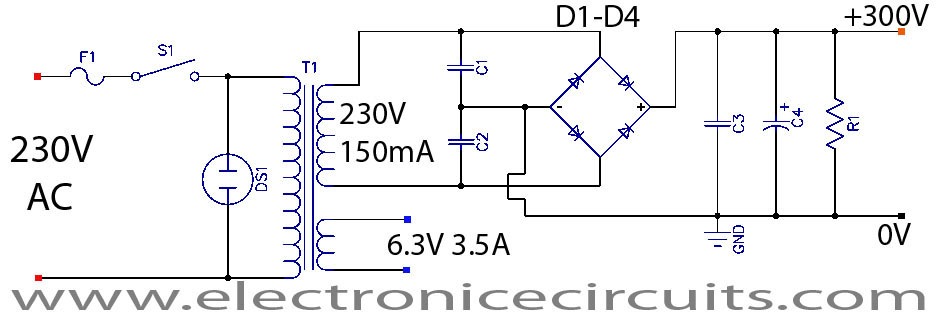
Im not suggesting using a single wound transformer for the heater supplies. I get why that has to be centre tapped or 2 transformers wired together. Im talking about the raw B+ supply. Im referring to replacing the 500vct tx with the 2 phase rectification with a 275V single winding tx with a bridge rectifier to connect to L1 and C21.
This will give a higher raw B+ but as the centre tap 65v elevation is after the 260v regulation stage that shouldnt be a problem. I just need to check that the possible 360v post rectifer/inductor wont be too much for the regulator. However, from the article....
"The sharp-eyed might have noticed that the transformer in the photo only has a 200V secondary. This was boosted to 230V by connecting the mains to the lowest primary tap. The raw B+ comes in at 285-300V, depending on the transformer, which allows a nice 25-40V cushion for the regulator (the higher the better)."
Ill stick look for a 1:1 tx if i can find it.
I just cant see why a bridge rectifier single end *wouldnt*(edit) work in this situation. What am i missing? One end can be tied to ground and the other end a rectifed HT supply to go to the smoothing, that then gets divided post reg for the heater supply elevation.
I read on valve wizard that you do get double the diode drop with a bridge rather than just 0.7v with a 2 phase but is that important?
Is 2 phase inherently better?
Cheers
Last edited:
im starting to collect bits for this build.
Ive found some siemens D3a from billington export in the uk
Do i need to buy matched pairs for this design? Im not sure what exactly they would be matching though. If they need matching in a specific way i could ask them if they do that.
Ive found some siemens D3a from billington export in the uk
Do i need to buy matched pairs for this design? Im not sure what exactly they would be matching though. If they need matching in a specific way i could ask them if they do that.
MrDave; I started to build this preamp, and switched to the MM EO design. I have a few extra bits for this that I'll sell cheap. The most important is probably the Decor power transformer. The EO design uses a much lower plate voltage, so I had to go to a different power transformer. If you are interested, I'll go figure out what I paid for it, and sell it to you for some fraction of the original price. It is new, but it has the leads cut to length, since I built it and then changed my plan.
Scott
Scott
Hi cogeniac,
Thanks for that. From your profile it looks as though youre in the US. Im in the UK and so need 240v so needed to select slightly different models than what was listed on the parts list. Just added up the edcor products and the postage is about 94 dollars so having another think.
Which one have you got?
Thanks
also just ordered my d3a and usually go for the EH6922 gold pins. Have used those for various things and have always seemed pretty good (thanks jackinnj)
About to order sowter 1480s but, my goodness, theyre pricey but should be top notch. (£250 for the pair). Theyre the replacement for the 8055.
Yeah, shipping the transformer to the UK is probably not cost effective. That sucker is heavy!
I have the Edcor XPWR100-120, so that clearly is not going to help you (I was hoping it might have a dual primary, but no such luck.
Good luck on your build! I also have four NIB/NOS Siemens gold pin D3A (7721) tubes (the EO only uses EC88's). I got them from a guy in Germany on eBay. IIRC they were about $US110 including shipping for the set. Let me know if you are interested in those.
The Cinemag transformers are used in a number of "step-up" designs -- check out the review section of Stereophile for phono preamps. I think that Dave at Cinemag uses Studio Electronic to move product through ebay.
you can also check out the Shure 1:10 microphone transformers which regularly feature on EBay.
you can also check out the Shure 1:10 microphone transformers which regularly feature on EBay.
Last edited:
thanks guys, ill bear the tubes in mind.
Ive found studio electronics on ebay but the cinemag 1254 is even more expensive than the sowter! £140 ($180) per can plus postage and import etc.
Sowter also do a slightly cheaper model, the 9570 which i think is suitable but this wouldnt allow me to drop to 1:5 if im finding it all a bit hot with my cartridge.
looking at the stereophile reviews, bobs devices come up a lot but he gets the 1131, a hand 'made by dave' version of the 1254 and other models use cinemag sky, but theyre not on the cinemag website so im wondering if he got them custom made.
Havent found out much about the shure.
It does look like the sowter 1480 is quite a bit better than the 9570 though.
ha, yes. Just used the way back machine. in 2010 about £71 +vat (15% i think). and £81 +vat (20%) in 2015.
I suspect this is quite a critical part of the whole project so probably not worth skimping on. Ill build it once and thatll be that!
Any news on the boards?
Thanks
D.
I suspect this is quite a critical part of the whole project so probably not worth skimping on. Ill build it once and thatll be that!
Any news on the boards?
Thanks
D.
I have a few questions regarding the power supply for the EO preamp.
SY says that the balanced heater supply can be used for the EO, but that one needs to change the voltage for the tubes used. He gives an example in the EO article about using +/- 3.15 volt regulators for a 6.3 volt heater (which is what I need for my ECC88 tubes.
HOWEVER, his schematic shows the heaters connected between each regulator output and the heater common. If that was the case, then the voltage on each heater would only be 3.15 volts.
Like this:
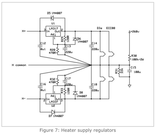
I built up the heater regulators and the preamp boards. I have hooked up the tube heaters ONLY (not ready to try connecting the plate and cathode supplies). As expected, I measure 6.3 volts (OK, it's actually 6.4) between the positive regulator output and the negative regulator output.
If I connect one heater connection to the negative regulator, and the other to the positive, the tube heater glows (as expected). If I hook it up between one regulator and ground, the heater doesn't heat up (as expected). So this seems to argue for hooking them up n this manner (and it also makes more sense relative to running them balanced to eliminate common mode noise (otherwise how is it that running one tube form one reg and the other from the other reg would provide any noise benefit? ).
So my initial questions are:
1) Is the HMN heater schematic incorrect, and should I be running one heater terminal from the negative reg and the other from the positive reg?
2)If not, then should I set the regulators to 6.3 volts each, and run one tube from each one?
3) if the answer is #2 above, then how is it that this balanced heater scheme provides any noise rejection?
My other issue is that if I let the regulator run without being connected to anything, it is stable and runs cool. HOWEVER, when I put the tubes in, the the regulators get super hot, and after only about 1 minute they go into thermal shutdown. I suspect this is because I used the original HMN raw supply that puts out about +/-13 volts, and at 365 mA of heater current per tube, I get about 3.6 watts of dissipation. I'll try using a lower voltage raw heater supply, and see how that works.
Scott
SY says that the balanced heater supply can be used for the EO, but that one needs to change the voltage for the tubes used. He gives an example in the EO article about using +/- 3.15 volt regulators for a 6.3 volt heater (which is what I need for my ECC88 tubes.
HOWEVER, his schematic shows the heaters connected between each regulator output and the heater common. If that was the case, then the voltage on each heater would only be 3.15 volts.
Like this:
I built up the heater regulators and the preamp boards. I have hooked up the tube heaters ONLY (not ready to try connecting the plate and cathode supplies). As expected, I measure 6.3 volts (OK, it's actually 6.4) between the positive regulator output and the negative regulator output.
If I connect one heater connection to the negative regulator, and the other to the positive, the tube heater glows (as expected). If I hook it up between one regulator and ground, the heater doesn't heat up (as expected). So this seems to argue for hooking them up n this manner (and it also makes more sense relative to running them balanced to eliminate common mode noise (otherwise how is it that running one tube form one reg and the other from the other reg would provide any noise benefit? ).
So my initial questions are:
1) Is the HMN heater schematic incorrect, and should I be running one heater terminal from the negative reg and the other from the positive reg?
2)If not, then should I set the regulators to 6.3 volts each, and run one tube from each one?
3) if the answer is #2 above, then how is it that this balanced heater scheme provides any noise rejection?
My other issue is that if I let the regulator run without being connected to anything, it is stable and runs cool. HOWEVER, when I put the tubes in, the the regulators get super hot, and after only about 1 minute they go into thermal shutdown. I suspect this is because I used the original HMN raw supply that puts out about +/-13 volts, and at 365 mA of heater current per tube, I get about 3.6 watts of dissipation. I'll try using a lower voltage raw heater supply, and see how that works.
Scott
- Home
- General Interest
- diyAudio.com Articles
- His Master's Noise: A Thoroughly Modern Tube Phono Preamp