OK, I'm looking at the design more closely and I notice that you have the D3a running with an elevated heater as with the output tubes, is there any disadvantage to doing this?
Also, you have a split heater positive and negative supply to the heaters when they are all 6.3V, why not put them all on the positive and eliminate the negative. There are higher current 3 terminal regulators such as the LM350. I could see if you were using some OP amps but? Also the transformer is center tapped so change it to a full-wave for fewer parts, double up on capacitance for equal smoothing if that even matters. Then the negative regulator can be eliminated. Considering how few parts the actual amp has it is a worthwhile change in my opinion.
What are the first two plate voltages and the output cathode voltage just to know as a sanity check for debugging?
Last edited:
Elevated heater can eliminate a source of noise from the heater to the cathode.
The split supply is likewise designed to eliminate a noise source from the heater, in this case common-mode noise. Conventional heater regulation schemes only bypass differential mode noise.
It's been a while since I probed in there, but if memory serves, the D3a plate voltage is about 150-160V, the ECC88 is about 90V.
Very interesting thread.
I was in the market for a good phono preamp, so this seems to fit the bill.
The Sowter transformers are pretty pricey, but I like the design approach. Looks like I can build the entire thing for about $600 plus some chassis parts.
My approach here is to lay out the preamp signal stages as a dual preamp board. That makes for a more elegant physical layout. My Eagle PCB software limits me to the board size I can use, so I had to put the larger caps (C4 & C5) on end on the bottom of the board.
Since the heater supply is on a separate board, I decided to simply put screw terminals on the bottom of the board and wired up each tube heater separately. That avoids running heater lines all over the board along with the signal traces. Simple layout, and less potential for noise.
I'll probably do a dual HV supply board as well.
I'll keep you posted!
Scott
Last edited:
I have the signal board laid out. Still need to do the hearted and regulator board.
Once I have that done, and have tested it out, I'll make them available. I built a transistor Beta matcher over on the Solid State thread,and after fixing an error on the board plan to post the files. The moderator there is talking about maybe having the DIY Audio store make and sell the boards.
I'll keep you posted.
I'd be interested to hear from SY about partitioning. Is there any issue doing both right and left signal circuits on one board, and then doing a separate board for the regulators?
For esthetics, I put the tubes in the corners of a 6x4 board. I then put two 1/2 inch holes in the middd of the board to accommodate the transformers. I plan to use a piece of polished stainless with four holes cut for the tubes, so they will stick out above the polished panel. I will then mount the two Sowter transformers on that between the tubes. The threaded mount for each transformer will then go through the board and will connect to the phone input jacks and screw connectors on the signal boards. The Sowter's are no particularly pretty, but they are functional looking, so the overall package should look purposeful. I'll mount the signal board to the plate using rubber grommets to reduce microphonics, per the article.
I plan to keep the raw supply separate as was done in the original post.
Scott
Is there any issue doing both right and left signal circuits on one board, and then doing a separate board for the regulators?
None that I can see as long as you have some local bypassing on the signal board.
Here's the signal board. I'll post the fab files once I am sure it works.
I laid this out wight he components on one side, and the tubs on the other. That allows me to put the board close to the top plate of the chassis and the tubes will stick out through holes for cooling. That's why the tube socket numbering is mirror image.
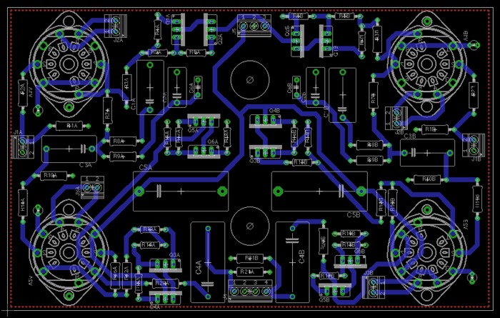
As noted above, I have separate heater screw terminals for each tube, a screw terminal for the HV supplies, one for each input and one for both outputs. The two holes in the board are to let the Sowter transformer mounting sleeve extend down through the board. I have still to add mounting screw holes.
Cheers.
Scott
I laid this out wight he components on one side, and the tubs on the other. That allows me to put the board close to the top plate of the chassis and the tubes will stick out through holes for cooling. That's why the tube socket numbering is mirror image.
As noted above, I have separate heater screw terminals for each tube, a screw terminal for the HV supplies, one for each input and one for both outputs. The two holes in the board are to let the Sowter transformer mounting sleeve extend down through the board. I have still to add mounting screw holes.
Cheers.
Scott
Last edited:


")


I just went over a couple dozen reviews of phono-preamps in Stereophile. The best which JA had reviewed (Boulder 1008, $12k) MC section had THD+N% of 0.065% The HMN is about 0.02% JA mentioned that the Boulder had overload margin (1% THD) of 33dB relative to 5mV for the MM section. Bit of an apples to oranges comparison, but the HMN isn't even perspiring at +33dB relative to 500uV (considering that it is designed for MC carts.) JA doesn't provide an overload margin for the Boulder's MC section.
In fairness, the Boulder is quieter than the HMN.
In fairness, the Boulder is quieter than the HMN.
- Home
- General Interest
- diyAudio.com Articles
- His Master's Noise: A Thoroughly Modern Tube Phono Preamp