As of today, I can boast that I also have a Le Monstre amplifier, currently in the JLH69 box and with its regulated, +/- 19V supply, current through the output transistors is 1A, transistors are 2SK170 / SJ74 + 2SC3324 / SA1312, 2SC3467 / SA1370 and output pair 2SC4467 / SA1694.
It works perfectly, I'm satisfied. The sound is great. It's not like my version of the JLH69, but I've been working on it for almost a year to perfection, I also need to give Le Monster a chance, I still have plenty of transistors to try, though it sounds great as well.
Great job!
Just a quick question: Since this amplifier is in my future plans, what PCB design did you use for your build?
Great job!
Just a quick question: Since this amplifier is in my future plans, what PCB design did you use for your build?
I do PCB design by myself, a true d.i.y.
")
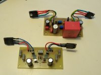
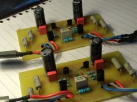
in the first picture above is a PCB of JLH69, below is a PCB for Le Monstre
Attachments
Did you get your problems sorted with the Serbian kit? I purchased on and the 5w, resistors run extremely hot and the voltage drop from the power supply seems excessive - from 12.6 volts when not hooked to the boards down to 6.8volts when running.
I don't know, I didn't see that KIT from Serbia, maybe something was wrong-fused on PCB or something was short-circuited or maybe it had some fake part. These are high currents when there is so much voltage drop, over 6A.
Put a picture of the PCB so we can see the transistors.
The parts look legit and I used input jfets from DIY audio store (linear systems matched)
The ebay listing is here:
https://www.ebay.com/itm/Hiraga-Le-...e=STRK:MEBIDX:IT&_trksid=p2057872.m2749.l2648
The ebay listing is here:
https://www.ebay.com/itm/Hiraga-Le-...e=STRK:MEBIDX:IT&_trksid=p2057872.m2749.l2648
hiraga sound problem
Hi all,
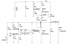
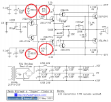
I build hiraga amp 2 channel using below schematic. Sound is good.
But last week i have issue for one channel.Sound like not enough power(hard to say,still have song).Another channel work excellent.
I measure at red point is -5.05V. Can somebody guide me to troubleshoot this amp?
One more question how to set bias this amp using trimmer?what value of trimmer pot ?
Thanks
Hi all,
I build hiraga amp 2 channel using below schematic. Sound is good.
But last week i have issue for one channel.Sound like not enough power(hard to say,still have song).Another channel work excellent.
I measure at red point is -5.05V. Can somebody guide me to troubleshoot this amp?
One more question how to set bias this amp using trimmer?what value of trimmer pot ?
Thanks
Attachments
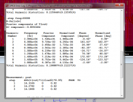
It is fully possible to increase to +16/-16 supply.
This almost doubles the power output.
Bias should be increased to 1.0 Ampere
Like here. See image.
THD 0.200% 10.75 Watt +16/-16 Volt supply
compared to 5.87 Watt with +12/-12 supply
Hi,what software you use for circuit simulation?
Hi "grunf"
Could I ask for some details of the regulator circuit that you used, and will it work for the 30W version?
I made this regulator for my version of the JLH69 amplifier.
The output voltage can be adjusted, tested at 4A, with a minimum voltage drop of 3 V. It is a high-current version of Walt Jung's superregulator.
https://www.diyaudio.com/forums/solid-state/3075-jlh-10-watt-class-amplifier-563.html#post5972683
https://www.diyaudio.com/forums/solid-state/3075-jlh-10-watt-class-amplifier-580.html#post6050539
Attachments
Hi,what software you use for circuit simulation?
My Le Monstre works at +/- 19V, at 14W at 8ohm distortion should be about 0.2%. The current is 1A.
Attachments
My Le Monstre works at +/- 19V, at 14W at 8ohm distortion should be about 0.2%. The current is 1A.
Thanks for reply,
Which component i need to change to use +-16V POWER SUPPLY?
Using below circuit.
Attachments
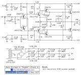
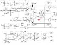
You should go back to the original Hiraga Class A (low power version). This is over 30W and it was modified based on that.
Take a look at these schematics.
You get the idea of how many changes you need. I prefer the second schematic over the first. I built and tested both!
Take a look at these schematics.
You get the idea of how many changes you need. I prefer the second schematic over the first. I built and tested both!
Attachments
You should go back to the original Hiraga Class A (low power version). This is over 30W and it was modified based on that.
Take a look at these schematics.
You get the idea of how many changes you need. I prefer the second schematic over the first. I built and tested both!
Oh no..difficult to me to modified.
.Some body can guide me?Can only change zener diode?
Oh no..difficult to me to modified.
Some body can guide me?Can only change zener diode?
I think i need to change red component.Zener diode 22 to 12v.And resistor from 4.7k to 10k for run in 16v dual power supply.
Which resistor control bias?
Attachments
There is not a single resistor which controls or set the bias, it is a compound circuit. When changing the value of the power rails, you better calculate everything again. But keep the first stage on the original lower (zener-) value. No need to change that (save the series resistor in value and dissipation).Which resistor control bias?
Settings are mainy with the collector resistances.
Grunf
Nice work.
I see that you used ZLJ capacitors in Hiaraga and FC and KMG or some others at JLH. ZLJ are quite *dry* and little *light* e sounding compare to for example Muse ore Silmic . Also FC that you used at JLH are for my ears fuller and little rounded. If sound is little sharp than maybe try other caps.
- Home
- Amplifiers
- Solid State
- Hiraga "Le Monstre"