Hi Zen mod, Hi Eduard,
Higher DC Res. = larger voltage drop smaller overall size however heat dissipation becomes an issue due to losses.
lower DC Res. = less volts drop but much larger choke due to thicker winding wire and large core to accommodate it. however losses are reduced.
For the hiraga you need to handle about 1.5A per channel so 3A total
I have a couple of chokes to try different core shapes and sizes which are designed for about 3.2A.
I will do a couple of measurements under load and let you guys know what i find.
-Dan
- also the heatsinks will be bolted flat to the chassis as is,
so the chassis itself will have some contribuation to heat dissipation.
which it will regardless.
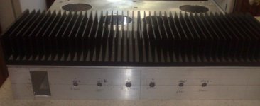
I have actually tested a smaller version of this heatsink and it is capable of running cool enough to touch without burning someone. running 1.5 A bias. on the hiraga.
the pic may be deceptive of the heatsink(s) overall size.
it is ~35 x 150 x 420 mm total.
Rth by calculation is 0.12025 deg. C/W for 80C rise
(in practice the rise is nothing like 80C this is just maunfacturers data used in calc.)
so i expect about 25K rise.
34V*2(supply rails)*1.5A=102W*2(channels)=~204W total
204W*0.12025deg. C/W = 24.531 K rise.
-Dan
-Dan
so the chassis itself will have some contribuation to heat dissipation.
which it will regardless.
I have actually tested a smaller version of this heatsink and it is capable of running cool enough to touch without burning someone. running 1.5 A bias. on the hiraga.
the pic may be deceptive of the heatsink(s) overall size.
it is ~35 x 150 x 420 mm total.
Rth by calculation is 0.12025 deg. C/W for 80C rise
(in practice the rise is nothing like 80C this is just maunfacturers data used in calc.)
so i expect about 25K rise.
34V*2(supply rails)*1.5A=102W*2(channels)=~204W total
204W*0.12025deg. C/W = 24.531 K rise.
-Dan
-Dan
Choke input or no choke input.
To use a choke or not to use a choke....
I have quickly done the test in my lunch break....
Circuit:
Single rail linear supply with bridge rectifier.
Xfrmr and rectifier common throughout.
Results:
first test:
100 000 uF 63V RIFA industrial high current cap.
ripple @ 35V 3A resistive load = <8mV with or without choke.
clearly this cap is doing the job. but doesnt help me with my test...
second test:
10 000 uF 40V no name brand low quality cap
ripple @ 35V 3A resistive load = 647mV (no choke)
easily measurable ripple. its time to see if the choke helps much
third test:
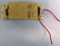
choke input filter (using common lighting choke 1.7 Ohm DC res. ~170mH from measurement.
10 000 uF 40V no name brand low quality cap (after choke)
ripple @ 35V 3A resistive load = 47mV
So for me the results are pretty clear.
The choke makes a huge difference to the supply ripple.
The choke i used has been used alot and is discoloured from being overheated. The choke is a fairly standard lighting ballast.
Which are available for less than $50.
I think i will have to take Eduard's (good) advice here
-Dan
To use a choke or not to use a choke....
I have quickly done the test in my lunch break....
Circuit:
Single rail linear supply with bridge rectifier.
Xfrmr and rectifier common throughout.
Results:
first test:
100 000 uF 63V RIFA industrial high current cap.
ripple @ 35V 3A resistive load = <8mV with or without choke.
clearly this cap is doing the job. but doesnt help me with my test...
second test:
10 000 uF 40V no name brand low quality cap
ripple @ 35V 3A resistive load = 647mV (no choke)
easily measurable ripple. its time to see if the choke helps much
third test:
choke input filter (using common lighting choke 1.7 Ohm DC res. ~170mH from measurement.
10 000 uF 40V no name brand low quality cap (after choke)
ripple @ 35V 3A resistive load = 47mV
So for me the results are pretty clear.
The choke makes a huge difference to the supply ripple.
The choke i used has been used alot and is discoloured from being overheated. The choke is a fairly standard lighting ballast.
Which are available for less than $50.
I think i will have to take Eduard's (good) advice here
-Dan
Attachments
Hello Daniel and all the others,
Yesterday i did take a look at the 5r4gyb ( tube rectifier) data-sheet. With capacitor input the difference between dc voltage at half-load and full-load current is 170 volts . With choke-input this value will be just 40 volts. Allthough your amp is a class A design the current draw will not be like a load presented by a big power resistor.
With a choke in real life conditions the differences will be bigger. Lots of hiragas have been build here in europe and most people would complain about the cost for the power supply. Most of them were build with 6 times 68.000 mf like the original 20 watt version. Le classe A that i did make was using 4* 330000mf after the wire wound resistor but the kit version in France could also be made with the chokes ( but not as a choke input). The caps were used extremely close to their nominal voltage just 1 volt under. Choke-input would require a bigger margin i think. I think it would be safer to use just a small bleeder to have a current flowing no matter what will happen to the circuit. I also did insert a resistor on the primary side to keep the caps under a certain tension without drawing current just to give them an easier life. Switching on without it would make the lights go down for a second. I think the resistor did make the voltage on the caps go down about 50%.
I did read on a dutch side that the wire from the rectifier should go to the terminal from the choke that is the beginning of the winding.
Having certain chokes availabe ( but all the same current raiting?) is nice. Maybe the results measured will be about the same if you just stick to the kind of measurement described today. But probably during listening they will sound different. Probably not probably, some will have a bigger influence on the parts being close. Maybe do some test on your chassis without attaching the chokes before start drilling. In the past i did do some test with positioning of chokes using a high impedance headphone across its terminal. Turning ot just moving closer or away from another iron would change the noise on my ears. But these were lot of henries, i think with your coils it will not work. It is a very old trick but i forget how it works exactly. Of course no power supply on the headphone connection.
Hoping your enthousiasm will affect some others. In the pass labs group a lot has been said about chokes but not about the kind of solution you are using. greetings, Eduard
Hi Eduard,
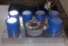
I am going to use a Pi section filter which is 200000uF then the choke then 2 x 200000uF caps, (for each rail) no resistors apart from the chokes copper resistance, the caps i am using are 50V working rating. and my supply voltage will be approx 34V dc per rail.
I have tested the supply already and the ripple is quite small even with out the choke so i am happy about that.
when i get a break from study/work/training/ bringing pa to a party
i will finish this thing off and listen to it properly (finally)
wish i had more free time !!!
-Dan
Hello Daniel,
Probably you wanted to have the extra output power that a cap-input would offfer compared to a choke-input because of the higher dc voltage. Sometimes measurements can't predict everything your ears will hear. My future drd vt25 will have a choke input, a second choke , general electric oil cap and some black gate wkz will be used 600hertz 12db and up and deliver about one and a half watts but with 109db 1 watt 1 meter there will be enough headroom.
A pity you didn't go all the way with what would have been the first hiraga amp with a choke-input power supply. I mean i never did see anyone using it.
But when you will not try it you will never gonna miss it. I still remember the first time i did hear vot's in Paris with a 2a3 or 6b4 single ended amp and i decided that i will have them in the future. But switching from low efficiency transmission lines with solid state amps to vot's with flea power takes decades for me. I have vot's for 15 years i think fleapower too but with el84 allthough i have a lot of vt25. But just like the most of us not enough time to get them going.
Greetings, Eduard
http://www.melaudia.net/ecouteSud04MR-1.php
Maybe you would like to take a look of my friends system in France. This is in a seperate building in his garden. A pity you can't read french. And it is not related to choke-input
Hi Eduard,
the power supply still has the same benefits of a choke input however the ripple is less before it gets to the choke.
are you suggesting i configure it as a pure choke input and then an RC filter or as pure choke input with no resistor at all maybe i am confused ?
either of these combinations is very easy to try once the choke/caps etc are in place it is just different configuration.
-Dan
P.S. that setups looks like the style in the L'audiophile setups in the magazines on CD-rom..... that is a serious listening room !!!!!!!!!
Hello Daniel,
With the line amps i have been using as a power amp for a long time now. I did change from cap input into choke-input using the same choke but of course a different hv transformer because of the voltage drop caused by the choke.. Later on i did switch to a tango choke designed for a choke-input onfiguration.
Changing into a choke input did surely give more detail but the big difference was that the amp did sound like somebody did add another amplifier to take care of the bass horn. It wouldn't run out of steam. You just want to turn up the volume every time you listen to it. These amps use the shunt regulation designed by allen wright. The circuit takes about 30 ma, the bleeder a little less and the shunt something like 60 ma if i am correct. The amp has negative feedback but in a special way, dont ask me to explain. So why would changing into choke-input be such a big difference???
Allen wright says the choke will work like an electronic flywheel.
So yes i think the choke should be directly after the rectifier ( i still think the 200000mf is big and will give it and the transformer a hard life with no choke involved. It might be a good idea to use a 0.1 ohm after the first cap.
Did you every hear about connecting an electric drill to the same 220 volts connection and look at the shape of the ripple when switching it on?
It is true once they are mounted it is just changing some wires but the configuration with the shortest connection can only be done when you will before if it will be choke input or not. The choke used as a choke input will have a bigger influence on the parts nearby.
The set-up of my friend has been described in France several times. He did work for the other french magazine called La nouvelle revue du son long time ago when that was still a serious magazine. He did write about his 211 single ended amp in l'' Audiophile. I should visit him again because he did make a lot of changes in his system.
Indeed a very serious listening . Just behind the bass horns which are part of the buiding is a small hall with a bathroom so you don't have to walk back to the house if you need to use it.
But just like many audiophiles he sometimes lacks the time to finish his projects. I did make several stainless steel chassis for him but so far he didn't use them. He wants to do it 110% . Another french audiophile i know will make a hard wire pulltec phono preamp in one day. I have the parts for this pulltec but just don't have enough desire to plug in the soldering iron. Once my projects will be finished i will just stick to making minor adjustments. Once i did have a phono preamp with did allready have a huge outboard power supply
a few thousend mf at 400 volts dc so a lot of stocked energy> I was in France in the shop of l''audiophile and one of the customers did advice to me to add a 3mf 1500volts paper in oil. Price was something like 20$ but the difference in sound was big. Brushes that have been allmost masked by noise did become clearer and easier to locate. I wonder if adding a paper in oil in an hiraga amp would give the same benefit. 6 mf 125volts dc philips can be found here for less then 4 euros . I use a similar one in my cross over. Did use scr csi mit there but the best were the philips and guess what they were the cheapest too.
Greetings, Eduard
Hi Eduard.
Its funny that you replied today because last night i marked out the chassis for the pcbs and out put stage to be mounted to.
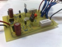
I have built an external DC detector circuit and mounted the heatsinks to the chassis.
once the last few holes are drilled the chassis will be painted.
I will post some pics up soon..
-Dan
Its funny that you replied today because last night i marked out the chassis for the pcbs and out put stage to be mounted to.
I have built an external DC detector circuit and mounted the heatsinks to the chassis.
once the last few holes are drilled the chassis will be painted.
I will post some pics up soon..
-Dan
Daniel
You use what schematic / devices?
How does this version differ from you published amplifier?
Jean Hiraga Le Monstre - by Daniel with Pictures!
You use what schematic / devices?
How does this version differ from you published amplifier?
Jean Hiraga Le Monstre - by Daniel with Pictures! SOUND
I am very pleased with the sonic results of this amplifier. It really does not disappoint. Even using fairly standard 3 way speakers in a large room, surprisingly there is ample power. What strikes me the most is the ability of this amplifier to differentiate between instruments and noises in the sound stage. This clarity is what I like most and I think this is achieved by Jean Hiraga's deceptively simple and pure circuit topology.
Overall I would recommend Hiraga's Le Monstre amplifier design to any one who appreciates listening to music.
you say you are very pleased with sound of this Class A amp
what other amplifiers you have to compare with, Daniel
Hello Lineup,
The semiconductor devices used are as per the origional
"Le Monstre" schematic diagram.
I have built a few other amplifiers in my time:
0.5 W champ amp = "POS"
LM1875 = ****
LM3876 = okay quite good for the effort involved
LM3886 = okay slightly more power than 3876
Digi125 = okay pain to build.
Denon HT amp = good
LG HT receiver = average
Plastic power 175W = okay a little harsh treble
Playmaster stereo (185W x 2) okay grainy / harsh treble
350W mosfet (altronics) = nothing special
AV800 (Anthony holton) = quite good
6AS7G push pull class A amp = okay but too underpowered for me
KT88 monoblocks (earlier pictured in this thread)
6L6GC monoblocks (earlier pictured in this thread same chassis)
5881 monoblocks (earlier pictured in this thread same chassis)
Ampslab HX100 7 channel = very good
Ampslab HX350 1kW monobocks = good suited to heavy duty
ACTRK600 high power version discussed at length in another thread
John Linsley hood Class A amplifier 1996 dual supply fully regulated version = excellent.
not really a definitive list but the Le monstre sonically is as good or better than any of these in my opinion.
the only problem is the lack of power hence me building the
Le classe A with a few more supply volts.
Hope this answers your question.
My stance orginally was amplfiers are sonically the same just power and volume setting makes the difference.
currently I think there are more subtle differences between them.
-Dan
lineup said:Wooow, Dan.
You have a lot of amplifier experience.
have a good day, danieljw .. here is very warm & sun today
(north sweden = top europe)
Hi Lineup,
It has been a bit of a hobby for a while.
North sweden, I am jealous sunshine and pretty girls come from sweden
Adelaide is cold and dark at the moment !
-Dan
Attachments

- Status
- This old topic is closed. If you want to reopen this topic, contact a moderator using the "Report Post" button.
- Home
- Amplifiers
- Solid State
- Hiraga 20W class A