Thanks Andrew Very appreciated
So is there a way for me to tell what the current limit Class-A is ? I have not the understanding, perhaps to be safe I should just stick to the schematic which says 0.4 to 0.5v across the resistors.
I suppose without an oscilloscope it makes things harder too ? Ive never owned a scope.
So is there a way for me to tell what the current limit Class-A is ? I have not the understanding, perhaps to be safe I should just stick to the schematic which says 0.4 to 0.5v across the resistors.
I suppose without an oscilloscope it makes things harder too ? Ive never owned a scope.
For a push pull output stage, the Current limit for max ClassA is just a little bit less than twice the bias current.
for 0r47 with Vre = 26mV the optimal ClassAB bias is ~55.3mA
The maximum ClassA is <110.6mApk
That equates to <49mW into 8r0.
Increase Vre to 47mV and peak ClassA increases to <200mApk
That now equates to <160mW into 8r0.
All the output below 200mApk stays in ClassA and there is no crossover distortion.
The maximum ClassA output power has tripled by changing the Vre from 26mV to 47mV
If you double the bias yet again to 94mVre, then the maximum ClassA output power will quadruple.
Last edited:
Input PSU
Hi, In regard to your question about a separate PSU for the input, I can tell you that this makes a HUGE difference. Keep in mind that zeners are noisy. Even if you devide the zeners up in three you will have a big difference.
I used 22V super regulator boards with ultra clean power and low impendance to power the input stage.
The cleaner it is, the clearer it will sound.
I also made an amlifier wit on board Kubota regulators for the first stage power. This is also a HUGE step up from standard zeners, and cheeper than separate super regs.
Cheers,
Sjoerd
1.Did anyone tried the Super class A with cap multiplier?
What differences have you noted between CM and a classic PSU (CLC recomended by Hiraga) in terms of sound reproduction (dynamics, clarity) and ripple?
I want to hear some impressions about this mod because i want to know in wich PSU to invest for this amp.
I'm interested in "Mr Evil Cap Multiplier", what do you all say?
2. Did anyone tried to do a second psu just for the input? What differences made?
3. What trannies should we use for the output stage because the 2sa/2sc pair are fake in my country and very hard to find?
Thanks in advance
Hi, In regard to your question about a separate PSU for the input, I can tell you that this makes a HUGE difference. Keep in mind that zeners are noisy. Even if you devide the zeners up in three you will have a big difference.
I used 22V super regulator boards with ultra clean power and low impendance to power the input stage.
The cleaner it is, the clearer it will sound.
I also made an amlifier wit on board Kubota regulators for the first stage power. This is also a HUGE step up from standard zeners, and cheeper than separate super regs.
Cheers,
Sjoerd
Member
Joined 2009
Paid Member
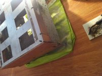
...d after I did the transfer from metal to wooden case the soundstage became almost twice as big. Low level detail was much better and the amp was still dead quiet. No noise, no hiss even on 116 dB/w/m horn tweeters.
I've noticed a few people, here and there, have had similar observations. There is something to learn here, something not fully appreciated.
You might also be interested in this: About DNM Design - Different Thinking in High End Audio
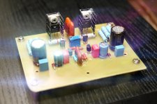
Jean Hiraga's Super Class A 30W Amplifier.
Dual Mono CRC 0,202F per channel. Transformers: 2xILP 2*18V*4,4A (160W). Bias: 1,7A.
Resistors: SMD 1206 Yageo 0,5% and Yageo MF-2 5%. "Sound's stream" C2-29B and C2-10 0,25% 25 ppm. Feedback C2-29B 0,1% 15 ppm.
Transistors: PH BC550C+ON BC560C, ON MJE15034G+MJE15035G, ON MJL3281AG+MJL1302AG.
p.s.: case not ended.
Attachments
-
 hiraga 30W_sm_01.JPG831.5 KB · Views: 1,136
 -
 50Hz and 100 Hz Noise Max Level.jpg437.3 KB · Views: 314
 -
 hiraga 30W_sm_15.jpg216.8 KB · Views: 363
 -
 hiraga 30W_sm_19.JPG919.5 KB · Views: 285
 -
 hiraga 30W_sm_18.JPG748.2 KB · Views: 248
 -
 hiraga 30W_sm_16.JPG738.2 KB · Views: 265
 -
 hiraga 30W_sm_14.JPG825.7 KB · Views: 943
 -
 hiraga 30W_sm_11.JPG940.2 KB · Views: 998
 -
 hiraga 30W_sm_10.JPG767.3 KB · Views: 1,004
 -
 hiraga 30W_sm_05.JPG883.5 KB · Views: 1,074
Last edited:
Thanks.Nice work Damon
On my ears the sound of "30W" better, than "20W". The sound of the 30W version of a cheerful and transparent. At 20W versions sound closer to the vacuum tube (I thought), of course, too good, but it's a bit not my thing.
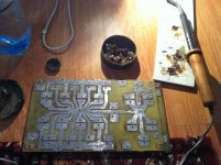
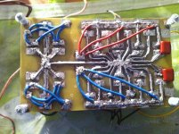
PCB its own.
Unfortunately, couldn't find the original drivers: 2sc1096+2sa634.
2sc1775+2sa872 reserved for "Le Monstre 8W".
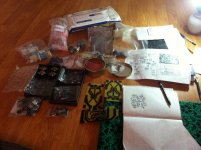
My version of the super class a 30w
Hello my friends,
Bellow are the pictures of the work in progres for my version. I should tell you something about it.
I have bought allot of components for good matching and three sorts of transistors for the driver and output wich will be tested and i will post the results with all of them. (Thank you very much OZAM for the help with these).
Input: bc550/560c nxp (ex philips)-- they have a low cob----beta around 560 (1% matching from 150+150pcs for each pnp and npn).
Drivers for test:
Vcbo Ic P Ft Cob
A. 2sa1930/2sc5171 180 2A 20w 200mhz 26pf
B. 2sa1120a/2sc2690a 180 1.2A 20w 175mhz 26pf
C. 2sa1837/2sc4793 230 1A 20w 70mhz 30pf
D. 2sa634/2sc1096(ORIG) 40 3A 10W ? 55pf (Idont have them)
All of them have the highest ranking for higher beta and i have 10 pcs from each of them for matching.
As you can see above all of these have better propreties than the original ones wich are now obsolete.. (I use the original ones here just for comparison)..
Output trannies:
a. mj21194/21195+mjl21194/21195 (2+2 pairs 10%matched) (4mhz@500pf@200W)
b. mjl4281/4302 (2 pairs 10%matched) (35mhz@600pf@230W)
c. 2sc5200/2sa1943 (4 pairs 10%matched) (30mhz@200pf@150W)--original ones
d. 2sa1492/2sc3856 (4 pairs but just two are 10%matched) (20mhz@500pf@130W)
e. TP2788 (specially matched pair for La Maison@L'Audiphille--obsolete from the 30w article and the 30w version) (i dont have them) (12mhz@170pf@80W)..
All the resistors are 1% metal film. The 68pf caps are silver mica 1%. The 150pf is a hv 3kv one and the rest are pp.
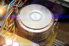
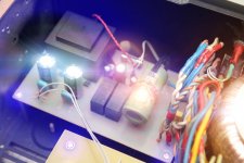
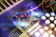
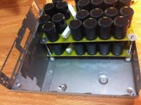
The config is for a dual mono 24v+24v cc @300w@ 22+22v ca each bicafilar winding and separate Ual for the input.
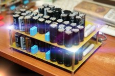
Both psu's are CrC (6x22000/35v+2x1ohm/20w+16x22000 for the output+2x2.2uF/450v decoupling caps) + (10000/35+0.5/6w+10000/35 for the input) for each channel, cumulating a total of 968.000uF for the output and 80.000uF for the input (i'm planing a JLH cap multiplier psu in the future for the input).
Diy audio soft start because of the big capacitance.
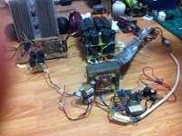
Bellow are the pictures made in order (as i finished the amps).
Hello my friends,
Bellow are the pictures of the work in progres for my version. I should tell you something about it.
I have bought allot of components for good matching and three sorts of transistors for the driver and output wich will be tested and i will post the results with all of them.
(Thank you very much OZAM for the help with these).Input: bc550/560c nxp (ex philips)-- they have a low cob----beta around 560 (1% matching from 150+150pcs for each pnp and npn).
Drivers for test:
Vcbo Ic P Ft Cob
A. 2sa1930/2sc5171 180 2A 20w 200mhz 26pf
B. 2sa1120a/2sc2690a 180 1.2A 20w 175mhz 26pf
C. 2sa1837/2sc4793 230 1A 20w 70mhz 30pf
D. 2sa634/2sc1096(ORIG) 40 3A 10W ? 55pf (Idont have them)
All of them have the highest ranking for higher beta and i have 10 pcs from each of them for matching.
As you can see above all of these have better propreties than the original ones wich are now obsolete.. (I use the original ones here just for comparison)..
Output trannies:
a. mj21194/21195+mjl21194/21195 (2+2 pairs 10%matched) (4mhz@500pf@200W)
b. mjl4281/4302 (2 pairs 10%matched) (35mhz@600pf@230W)
c. 2sc5200/2sa1943 (4 pairs 10%matched) (30mhz@200pf@150W)--original ones
d. 2sa1492/2sc3856 (4 pairs but just two are 10%matched) (20mhz@500pf@130W)
e. TP2788 (specially matched pair for La Maison@L'Audiphille--obsolete from the 30w article and the 30w version) (i dont have them) (12mhz@170pf@80W)..
All the resistors are 1% metal film. The 68pf caps are silver mica 1%. The 150pf is a hv 3kv one and the rest are pp.
The config is for a dual mono 24v+24v cc @300w@ 22+22v ca each bicafilar winding and separate Ual for the input.
Both psu's are CrC (6x22000/35v+2x1ohm/20w+16x22000 for the output+2x2.2uF/450v decoupling caps) + (10000/35+0.5/6w+10000/35 for the input) for each channel, cumulating a total of 968.000uF for the output and 80.000uF for the input (i'm planing a JLH cap multiplier psu in the future for the input).
Diy audio soft start because of the big capacitance.
Bellow are the pictures made in order (as i finished the amps).
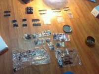
pics
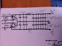
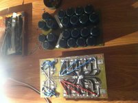
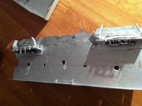
From left to right:
First pic is the same psu as mine, i use just one bridge pre total, and 24v output.
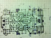
Second- the schematic.
3 and 4 --pcb
5-input psu
6-the caps
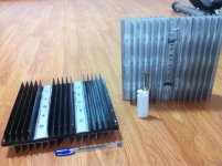
7-the radiators
8-etched pcb's
9 & 10 the amps assembled
From left to right:
First pic is the same psu as mine, i use just one bridge pre total, and 24v output.
Second- the schematic.
3 and 4 --pcb
5-input psu
6-the caps
7-the radiators
8-etched pcb's
9 & 10 the amps assembled
Attachments
-
 IMG_2606.jpg727.5 KB · Views: 259
 -
 IMG_2851.jpg619.6 KB · Views: 307
 -
 IMG_2831.jpg833.9 KB · Views: 246
 -
 IMG_2886.jpg719.1 KB · Views: 242
 -
 IMG_2827.jpg780.9 KB · Views: 308
 -
 IMG_2862.jpg668.8 KB · Views: 261
 -
 IMG_2864.jpg758.2 KB · Views: 228
 -
 IMG_2828.jpg890.8 KB · Views: 259
 -
 IMG_2846.jpg698 KB · Views: 270
 -
 IMG_2845.jpg647.3 KB · Views: 287
Last edited:
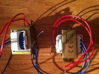
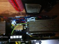
pics2
From left to right:
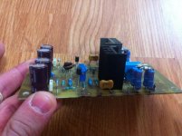
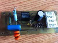
1- psu pcb
2- psu assembled
3- diy audio softy start
4 & 5 -- the diodes i used
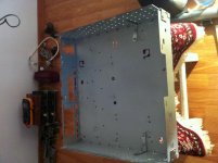
6-10-- the psu assembled in the actual modified Pentium 486 case
From left to right:
1- psu pcb
2- psu assembled
3- diy audio softy start
4 & 5 -- the diodes i used
6-10-- the psu assembled in the actual modified Pentium 486 case
Attachments
-
 IMG_2898.jpg673.7 KB · Views: 260
 -
 IMG_2909.jpg679.5 KB · Views: 160
 -
 IMG_2832.jpg704.2 KB · Views: 148
 -
 IMG_2988.jpg747.5 KB · Views: 199
 -
 IMG_2924.jpg799 KB · Views: 155
 -
 IMG_2860.jpg743.5 KB · Views: 185
 -
 IMG_2922.jpg639.6 KB · Views: 214
 -
 IMG_2943.jpg696.2 KB · Views: 158
 -
 IMG_2979.jpg647.3 KB · Views: 129
 -
 IMG_2985.jpg732.4 KB · Views: 123
Last edited:
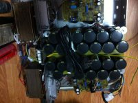
more pics
From left to right:
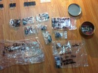
1-all the tranies
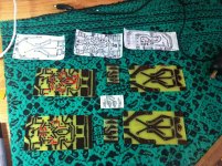
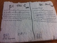
2-the poliester where i noted the different beta values for the input BC's (i noted just the paired ones)
3 & 4 - the tranies
5-trafos for the input psu
6- input psu+ amp
7- the amp in the case
8- the transformers
9- one chanel in test (the pic is made today)
From left to right:
1-all the tranies
2-the poliester where i noted the different beta values for the input BC's (i noted just the paired ones)
3 & 4 - the tranies
5-trafos for the input psu
6- input psu+ amp
7- the amp in the case
8- the transformers
9- one chanel in test (the pic is made today)
Attachments
-
 IMG_2880.jpg856.3 KB · Views: 547
 -
 IMG_2877.jpg705.4 KB · Views: 574
 -
 IMG_2824.jpg583 KB · Views: 595
 -
 IMG_2879.jpg725.6 KB · Views: 498
 -
 IMG_2910.jpg670.4 KB · Views: 461
 -
 IMG_2950.jpg696.9 KB · Views: 200
 -
 IMG_2994.jpg837.3 KB · Views: 181
 -
 IMG_2952.jpg581.6 KB · Views: 147
 -
 IMG_2951.jpg627.6 KB · Views: 185
Last edited:
Hiraga
I want to start a new thread about all the construction of this amp but after i will finish it.
Forgot to tell that the output resistors are 0.33/6w MO and the resistors for the psu's are wire winded.
All the pcb are coroded by myself and the pcb's are designed by me except for the soft start pcb.
I want to start a new thread about all the construction of this amp but after i will finish it.
Forgot to tell that the output resistors are 0.33/6w MO and the resistors for the psu's are wire winded.
All the pcb are coroded by myself and the pcb's are designed by me except for the soft start pcb.
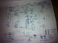
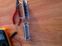
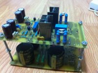
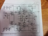
PLease help!!- High dc offset
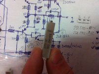
I fired up one channel and i've got on the output approx -1.5v ...
I tried to adjust but it doesnt go lower than -1.1v.
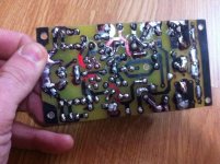
In the above picture are the actual measurements.
If i have 0.77 v across the output resistors means that i have 2.3A Bias??!!
Am i correct to adjust first the dc offset and then the bias or cand i lower the bias now?
I specified the transistors that i used in the picture.
Please help.
Cheers
Sergiu
I fired up one channel and i've got on the output approx -1.5v ...
I tried to adjust but it doesnt go lower than -1.1v.
In the above picture are the actual measurements.
If i have 0.77 v across the output resistors means that i have 2.3A Bias??!!
Am i correct to adjust first the dc offset and then the bias or cand i lower the bias now?
I specified the transistors that i used in the picture.
Please help.
Cheers
Sergiu
Attachments
Did you use 50ohm pot instead of 500ohm? You may only need a bigger potentiometer.
Yes, i used a 50ohm pot with two 110 ohm resistors in series for finner adjust of the offset. Now i'm replacing it with a single 500 ohm pot.
Did you use 50ohm pot instead of 500ohm? You may only need a bigger potentiometer.
With a 500ohm pot i got nearly -0.120 v but cant go lower than that. How can i further adjust this value to at least 80mv. Can i go to 1k pot?
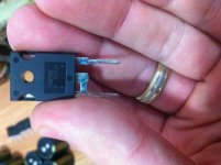
good offset adjust
Hi Daniel
Thank you very much for the sugestion but i can assure you that the matching is spot on with 1% match. I double checked the wiring..
After going to the local shop yesterday night for a night buy of fresh pots and after some tests i find something interesting.
From left to right:
In the 3d part of the l'audiophille (construction notes--pic 1 &2) there are some mistakes made on purpose by the auteur (i will kill him..).
The article is in picture nr2 (you have to rotate it) and is false (pic nr 6--number 1 on the sheet). With this setup you cannot adjust the offset.
I can only andjust the offset only with the setup in the picture nr 3,4 and 5 (with the type of pots described in the pictures).
In pic 7&8 is the trim pot that i use now and in the pic 9,10 is a russian type of trim pot that i luckly find on my local store and i want to change the pots with this type after final adjustments. This type looks like good quality to me.
I tried previously to adjust the offset with an 50ohm BOURNS 100ppm multiturn pot but i failed. This type of arrangement i like most (with series resistors because of the finner adjustment even with lower quality classic wiper trimpot).
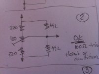
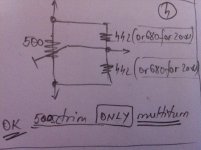
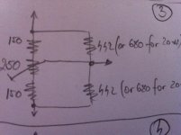
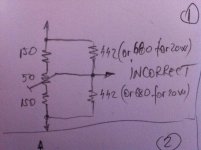
I studied abit the schematic and in the 20w version you had to have approx 180 ohm for each half of the 500 ohm trimmer + the 680ohm parallel resistors. In the 30 watts version you had to have approx 160 ohm for each half of the 500 ohm trimmer + the 442ohm parallel resistors (the variants bellow are calculated by me and succesfully tested).
Perhaps check the matching of the input transistors and that a resistor is not inthe wrong spot the offset is quite large I would have expected 1/10th of that dc offset value. Having said that reduce the bias first
Hi Daniel
Thank you very much for the sugestion but i can assure you that the matching is spot on with 1% match. I double checked the wiring..
After going to the local shop yesterday night for a night buy
of fresh pots and after some tests i find something interesting.From left to right:
In the 3d part of the l'audiophille (construction notes--pic 1 &2) there are some mistakes made on purpose by the auteur (i will kill him..
).The article is in picture nr2 (you have to rotate it) and is false (pic nr 6--number 1 on the sheet). With this setup you cannot adjust the offset.
I can only andjust the offset only with the setup in the picture nr 3,4 and 5 (with the type of pots described in the pictures).
In pic 7&8 is the trim pot that i use now and in the pic 9,10 is a russian type of trim pot that i luckly find on my local store and i want to change the pots with this type after final adjustments. This type looks like good quality to me.
I tried previously to adjust the offset with an 50ohm BOURNS 100ppm multiturn pot but i failed. This type of arrangement i like most (with series resistors because of the finner adjustment even with lower quality classic wiper trimpot).
I studied abit the schematic and in the 20w version you had to have approx 180 ohm for each half of the 500 ohm trimmer + the 680ohm parallel resistors. In the 30 watts version you had to have approx 160 ohm for each half of the 500 ohm trimmer + the 442ohm parallel resistors (the variants bellow are calculated by me and succesfully tested).
Attachments
-
 IMG_3003.jpg722.4 KB · Views: 237
 -
 IMG_3004.jpg824.7 KB · Views: 86
 -
 IMG_2999.jpg771.2 KB · Views: 118
 -
 IMG_3002.jpg789.2 KB · Views: 107
 -
 IMG_3001.jpg778.4 KB · Views: 108
 -
 IMG_2998.jpg782.4 KB · Views: 580
 -
 IMG_2995.jpg836 KB · Views: 115
 -
 IMG_2994.jpg778.6 KB · Views: 113
 -
 IMG_2996.jpg684 KB · Views: 137
 -
 IMG_2997.jpg592.9 KB · Views: 144
Last edited:
HELP! I cannot adjust Idle but the offset is ok!
Now i got +0.044V (44mV) offset with two 220 ohm resistors plus 100 ohm classic trimpot.
I have for the 1k8 bias resistors a 1k/1w trimpot + 1k8 MF 2w resistor per each half but i cannot go lower than 0.71V per half. If i increase the 1k trimpot to max (1k) the offset goes to -1.8v and the bias goes to 0.79v. This is crazy!!
The first setup was with the 1k trimpot with 910ohm 0.5W MO resistor but cannot adjust lover than 0.75v..
Last edited:
- Status
- This old topic is closed. If you want to reopen this topic, contact a moderator using the "Report Post" button.
- Home
- Amplifiers
- Solid State
- Hiraga 20W class A