Did anyone found some newer equivallent transistor versions for the original ones (with max 2pF Cob, low noise and hight gain)? I found that in my country are selled allot of fake 2sa970/2sc2240 so i dont want to purcase this version.
On ebay are some kits for sale with NJW0302G/NJW0281G, are they suitable for this amp?
On ebay are some kits for sale with NJW0302G/NJW0281G, are they suitable for this amp?
The Class A Amplifier Site is always a good starting point for these projects....The Class-A Amplifier Site - Jean Hiraga Index
The Class A Amplifier Site is always a good starting point for these projects....The Class-A Amplifier Site - Jean Hiraga Index
I have that site on mind but i was asking about suitable newer substitutes for the now obsolete transistors.
Thanks.
Or this site...Jean Hiraga's Super Class-A Amplifier
All the transistors 2SA872A, 2SC1775A, 2SA634, 2SC1096, 2SC5200 and 2SA1943 are avaiable from LittleDiode - Electronic Components Supplier
All the transistors 2SA872A, 2SC1775A, 2SA634, 2SC1096, 2SC5200 and 2SA1943 are avaiable from LittleDiode - Electronic Components Supplier
Last edited:
Or this site...Jean Hiraga's Super Class-A Amplifier
All the transistors 2SA872A, 2SC1775A, 2SA634, 2SC1096, 2SC5200 and 2SA1943 are avaiable from LittleDiode - Electronic Components Supplier
Thank you very much.
i would not trust them to be genuine. they also sell 2sj74 and they still order them in smal quantities. 99.8% of this transistors are fake. so where do they get them? no other company (other then fet audio that ordered a hell of a load a long time ago) have this in stock. at least not the real deal.
and even worse. the same is for 2sj109 no way they order this genuine j-fets this days. NO WAY there just is not possible for a company to order this fets any more.
and even worse. the same is for 2sj109 no way they order this genuine j-fets this days. NO WAY
Last edited:
Just stuffed aboard with the Fairchild KSA992 and the KSC1845 for the input, used a set of MJE15028 and 29 for the drivers and a set of 2SA1342/2SJ5199 as outputs, works like a champ. Bias resistors at 27K ohm results in 900mA bias current, will have to adjust that later for more current. R3 and 4 I have at 220 Ohms.
What is the criteria of selecting the imput trannies for this amp? Do we have to use the devices with maximum gain or with matched close gain? Just asking becuase of the diffrent values of the 200 respectively 300 ohms. I assume that they are there with different values because of this aspect. What do you say?
I used 220 Ohm for R4 and R4 and measure 980mV over R9 and R10 right on target with 0.8 to 1.0mA. I use 300R for the feedback resistor. I get most of my parts form Mouser and did not do any matching on the devices just picked them form the bin. I would assume that one could use the MJE 15030 and the MJE 15031 for drivers too
Heres a link
http://www.mouser.com/ProductDetail...=sGAEpiMZZMshyDBzk1/Wi8oN7VHZ91Okk2WNWq80Dmc=
Rail voltage is +/-31V and get 18V over a 8ohm load before clipping = 40W RMS
Square wave looks very nice too with no overshot or ringing, theres some slight rounding on the front edge when paralleling the 8 Ohm load with a 4.7uF cap.
Attachments
Hello,
Where did you find tha ksa/ksc pair for sale? Are they shipping to Europe?
Mouser stock them. They are really nice workhorses, I ordered 1000 of them...
Sajti
Hello,
Where did you find tha ksa/ksc pair for sale? Are they shipping to Europe?
The Input set I bought. One left! Be quick.
The Input set I bought. One left! Be quick.
The sale from the link isnt valid any more..
The Input set I bought on Ebay.
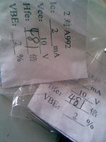
here is the set I received:

very well matched, it looks like (but of course at a premium price).
What is the criteria of selecting the imput trannies for this amp? Do we have to use the devices with maximum gain or with matched close gain? Just asking becuase of the diffrent values of the 200 respectively 300 ohms. I assume that they are there with different values because of this aspect. What do you say?
The difference between 200/240/300 ohms in the base is for matching differences in the base resistance; that will have an effect on the saturation; so in has nothing to do with tight matching of Hfe imho.
Saw also 2SA970/2SC2240 matched quartets, for USD 15 free shipping, is a good alternative too I think. Rbb is quite low as long as they are originals (I am so suspicious.. these days of fleabay)
i have built several hiraga's 20W with bc550/560 2sa970GR/2sc2240GR the bc were a bit muddy but fairly fine considering its hard to find original toshibas, i picked them up from old yamaha amplifier. as driver tried the 2sc3421Y/2sa1358Y also from the yamaha but they sounded light and plastic to me so changed them with mj15030/31 best till now, the curent OT are mj15003/04 and i've tried many other transistors these and 2sb688/2sd718 were the best of the bunch but mainly best results gave me whe i made it dual mono with 1000VA each and CLC filtering. hope this was helpful for someone.
I'm interested in trying the 30W version with +/-24V suply if anyone made the both 20W and 30W i would apreciate any sound comparison you made to share.
My hiraga doesnt have capacitors except at the zeners.
I'm interested in trying the 30W version with +/-24V suply if anyone made the both 20W and 30W i would apreciate any sound comparison you made to share.
My hiraga doesnt have capacitors except at the zeners.
I have a question about this topology. It appears to me that the input stage is outside of the global feedback loop. Is that correct, or am I missing something?
The literature on the Hiraga website seems to indicate that the feedback is primarily for DC stability. I have some ideas for variations of this circuit but I need to work on it more. I will definitely not have full gain down to DC and I will also not use a direct coupled input, for starters.
The literature on the Hiraga website seems to indicate that the feedback is primarily for DC stability. I have some ideas for variations of this circuit but I need to work on it more. I will definitely not have full gain down to DC and I will also not use a direct coupled input, for starters.
I have a question about this topology. It appears to me that the input stage is outside of the global feedback loop. Is that correct, or am I missing something?
The literature on the Hiraga website seems to indicate that the feedback is primarily for DC stability. I have some ideas for variations of this circuit but I need to work on it more. I will definitely not have full gain down to DC and I will also not use a direct coupled input, for starters.
The input is 'just' a buffer to raise the DC such that the 'real' input pair, the second pair, has the emitters roughly at 0V DC. And the feedback goes to these emitters. So that is the 'real loop'.
The AC-feedback is low, the output impedance is high, and many speakers shine with this amplifier.
- Status
- This old topic is closed. If you want to reopen this topic, contact a moderator using the "Report Post" button.
- Home
- Amplifiers
- Solid State
- Hiraga 20W class A
