I just realized that you are in a 60Hz area. This is perhaps the reason why the values I gave look unusual to you: everything else being equal, a 60Hz transformer will have a leakage (60/50)² times smaller than its 50Hz counterpart. That is almost 50% less.How are you going to get 1.28 mH of leakage inductance on the secondary side of the transformer?
This may look much, but it is still relatively minor compared to the variations caused by construction and winding techniques
Update:
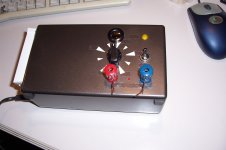
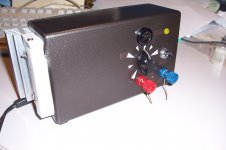
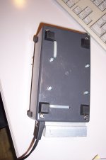
I have encased the combo supply. I managed to cram everything into a 19x11x7.5 cm³ box (7.5x4.4x3 in³).
It has the pleasant look and feel of a solid cast iron ingot, just a little bit heavier.
Unfortunately when I tested it, I realized that it had had a disastrous effect on the noise residues in the output: with the proximity of everything, inductive and capacitive couplings had predictably become unmanageable.
Since I didn't want to go back after such a feat, I had to add supplementary LC filters: they saved the day, and the worst case noise level is now a mere 50mV pp, very much less in rms.
The output goes smoothly from 0 to 400V, with a 1.1A current up to ~100V, and 250mA at 400V.
I have also added makeshift heatsinks on the main rectifier bridge: with the huge current, the 3A diodes became unbearably hot.
I even have some spare space in the box: maybe I'll add something one of these days: a meter or a standby switch.
Attachments
No problem, but note that these are problems of my own making: each bit taken separately and with enough space to breathe worked satisfactorily." I had to add supplementary LC filters" Can you explain or show were the LC filter goes with an updated schematic.
Only when I tried to cram everything into an unreasonably tight space did the problems appear. And as I said, they were entirely predictable. But the problem is that I had no master plan set from the beginning: I first explored the crypto concept, built a proof of concept prototype, found that it was viable and could be improved with a post regulator, added the post regulator on a test board that had never been intended to receive it, and ended trying to stuff the whole thing into a very tight case, because my lab is already clogged up with 1001 clever items.
I you don't suffer from similar behavioral troubles, there is no reason you follow the same path: you can start from a clean and well thought out layout, and put the thing into a spacious enough case.
It would even be possible to achieve similar compactness without the problems, but this would require careful thinking from the beginning; not after you notice the problems, as I did.
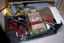
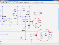
Anyway, here are the mods I carried out, highlighted in red: L2 and L3 are dual 100µH inductors (brick-colored in the pics)
Attachments

Hi Elvee,
just spotted this thread yesterday, and I became very interested in your supply: 1) uses cheap LV transformers, 2) same supply feeds from "current hungry" 6C33C up to "voltage hungry" 300B without requiring big transformers and/or big heatsinks. Only downside I see is that the eventual end product, including the series regulator, became quite complex. You still managed to put everything on a protoboard, but I think a PCB would be perfect... so, are you thinking about making a PCB available for this? I saw Rod Coleman has shown interest in this circuit as well, maybe he is willing to help (as I know he makes some nice PCBs).
I would, for sure, be interested in getting some - and I think a lot of other members as well, as adjustable PS makes life so much easier.
Cheers, Erik
It is (relatively) complex because it is a complete lab supply, going from 0 to 400V and having a good (albeit two level) current limiter.just spotted this thread yesterday, and I became very interested in your supply: 1) uses cheap LV transformers, 2) same supply feeds from "current hungry" 6C33C up to "voltage hungry" 300B without requiring big transformers and/or big heatsinks.
If you use only the crypto concept, it can still have an acceptable range of variability and offer decent performance with a much reduced complexity.
That is indeed the sensible option but ...but I think a PCB would be perfect...
No, sorry, I don't do PCB's: now that my prototype is up and running, I don't feel the urge to make it into something more rational....so, are you thinking about making a PCB available for this?
Let's hope someone takes that step....I saw Rod Coleman has shown interest in this circuit as well, maybe he is willing to help (as I know he makes some nice PCBs).
I would, for sure, be interested in getting some - and I think a lot of other members as well, as adjustable PS makes life so much easier.
Cheers, Erik
Note that the two parts need not be interconnected: the switching preregulator will work with any linear supply, and the opposite can be true if the preregulator is adapted.
Obviously, this tandem works well (that is currently my preferred of my three HV supplies), because one part has been designed the other in mind, but they can be reused in other ways
Hi Elvee,
thanks for your reply. I don't (I can't) do PCB's, unfortunately, otherwise I would take up the challenge. I understand that it doesn't require the big heatsinks, that is what I tried to describe as one of the big advantages.
Still many thanks for posting the design!
Erik
thanks for your reply. I don't (I can't) do PCB's, unfortunately, otherwise I would take up the challenge. I understand that it doesn't require the big heatsinks, that is what I tried to describe as one of the big advantages.
Still many thanks for posting the design!
Erik
Sorry, I read a bit too quickly... I have now deleted the PSI understand that it doesn't require the big heatsinks, that is what I tried to describe as one of the big advantages.
Hey ,this is a nice piece of work from my fellow countryman! This is actually a very good idea!The only downside isof this circuit is the unpredictable behaviour of the transformer in this case.High frequency parasitic behaviour is never specified for 50/60 Hz transformers.
I stumbled upon this thread because i was playing with the idea of putting a PFC behind a transformer.The classic way to build a power amplifier with a transformer/greatz bridge and electrolytic capacitor can be modified to a PFC version starting with a transformer of say 20-30% less output voltage.Now ,after seeing your post here, I think taht this will certainly work,but the big question is : how about the EMC behaviour? If this big power transformer starts to be a large HF emitter, radiating both electric and magnetic fields all over,we're just better off with the plain old XFMR/bridge/cap ,or go just all the way and make/buy a SMPS.
I stumbled upon this thread because i was playing with the idea of putting a PFC behind a transformer.The classic way to build a power amplifier with a transformer/greatz bridge and electrolytic capacitor can be modified to a PFC version starting with a transformer of say 20-30% less output voltage.Now ,after seeing your post here, I think taht this will certainly work,but the big question is : how about the EMC behaviour? If this big power transformer starts to be a large HF emitter, radiating both electric and magnetic fields all over,we're just better off with the plain old XFMR/bridge/cap ,or go just all the way and make/buy a SMPS.
As I said in the first post, it is not too unpredictable: it is dependent upon the transformer's construction which is rather obvious, even for the non-expert eyes.The only downside isof this circuit is the unpredictable behaviour of the transformer in this case.High frequency parasitic behaviour is never specified for 50/60 Hz transformers.
Anyway, the converter is current-mode, and is good at adapting to different parameters
It does certainly generate some EMI pollution, as any switching device, but it is manageable: if you use the preferred type of Xformer (EI side by side), grounding the core to the secondary will mostly eliminate the common mode coupling between primary and secondary, most of the differential switching residues reinjected through the primary are eliminated by the "X" primary cap, and the magnetic stray field is not particularly a problem, it decreases quickly with distance, you should just take care not to place sensitive circuitry too close. That is a sensible advice anyway, even for 50Hz.,but the big question is : how about the EMC behaviour? If this big power transformer starts to be a large HF emitter, radiating both electric and magnetic fields all over,we're just better off with the plain old XFMR/bridge/cap ,or go just all the way and make/buy a SMPS.
If you want to perfect these aspects, you can use the same techniques as with any other switcher: common mode chokes, screens, input and output differential filters, "Y" caps, etc
It depends on what you need (or hope for): the schematic in the first post is the simplest, and was the first to be actually tested.
It works well, but it won't go below the peak rectified output of the transformer you happened to chose: 40V in my case, which is immaterial if your target is a plain vanilla HV supply.
The output is like that of any basic SMPS, that means a little bit of switching ripple and also a large output capacitance: if the circuit you supply has a sudden problem, this kind of supply won't be able to protect it like a good linear supply would.
I wasn't ready to accept these (relatively minor) inconveniences, and I added a linear post-regulator, which transforms it into a near-perfect equivalent of a truly linear supply:
http://www.diyaudio.com/forums/powe...variable-supply-shoestring-2.html#post3391358
This is more complex, requires heatsinking and resistor matching but changes it into a true lab supply.
In addition, since I didn't foresee the transformations I would be making after my success, I had to address secondary problems: cramping all of that in a tight space created ripple feedthrough problems that I had to solve if I really wanted to benefit from the linear transformation, and this meant added filtering, etc, but this is of no concern if you plan the right version from the beginning: either the pure switching one having a moderate cleanliness, or the linear augmented one, in which case you must have sufficient room to avoid unplanned couplings that are expensive to remove afterwards.
Note that this scheme relies heavily on the parasitics of the transformer you use, and it is preferable to take this into account from the beginning, even if the tolerance is relatively high: basically, any type of EI transformer would do, but a toroidal would be more problematic.
If you give more details about your final target, and what components (transformer in particular) you are going to use, I will probably be able to give you some guidance.
Last edited:
It depends on what you need (or hope for): the schematic in the first post is the simplest, and was the first to be actually tested.
It works well, but it won't go below the peak rectified output of the transformer you happened to chose: 40V in my case, which is immaterial if your target is a plain vanilla HV supply.
The output is like that of any basic SMPS, that means a little bit of switching ripple and also a large output capacitance: if the circuit you supply has a sudden problem, this kind of supply won't be able to protect it like a good linear supply would.
I wasn't ready to accept these (relatively minor) inconveniences, and I added a linear post-regulator, which transforms it into a near-perfect equivalent of a truly linear supply:
http://www.diyaudio.com/forums/powe...variable-supply-shoestring-2.html#post3391358
This is more complex, requires heatsinking and resistor matching but changes it into a true lab supply.
In addition, since I didn't foresee the transformations I would be making after my success, I had to address secondary problems: cramping all of that in a tight space created ripple feedthrough problems that I had to solve if I really wanted to benefit from the linear transformation, and this meant added filtering, etc, but this is of no concern if you plan the right version from the beginning: either the pure switching one having a moderate cleanliness, or the linear augmented one, in which case you must have sufficient room to avoid unplanned couplings that are expensive to remove afterwards.
Note that this scheme relies heavily on the parasitics of the transformer you use, and it is preferable to take this into account from the beginning, even if the tolerance is relatively high: basically, any type of EI transformer would do, but a toroidal would be more problematic.
If you give more details about your final target, and what components (transformer in particular) you are going to use, I will probably be able to give you some guidance.
So as I understood. This power supply will be built based on my target and use the transformer parasitics. My target will be ~ 300V 100mA, I can only buy a 24VAC 60W transformer like my attach image. Do you think it is ok? If yes, I will buy it and try to measure its H.
Attachments
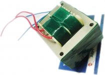
This type of transformer is ideal for this kind of supply, and 60VA for a 30W DC output is very generous since the circuit acts more or less like a PFC and has only a few watts losses.My target will be ~ 300V 100mA, I can only buy a 24VAC 60W transformer like my attach image. Do you think it is ok? If yes, I will buy it and try to measure its H.
The preregulator is a positive boost, but the linear post reg is a negative one, and the ground node has been placed at the most convenient place for simulation purposes.I'm struggling to understand the schematic; it seems that from the HV rail (noted PRE) from this post, the power must flow through R11, a 100K resistor. What's going on?
C11 is the output bypass, and R11 is the output bleeder.
Yes, that's somewhat disturbing, but you can redraw the schematic in a more convenient way, the operation won't change, the rest is just conventions...
So as I understood. This power supply will be built based on my target and use the transformer parasitics. My target will be ~ 300V 100mA, I can only buy a 24VAC 60W transformer like my attach image. Do you think it is ok? If yes, I will buy it and try to measure its H.
Measure secondary leakage H with primary shorted, is that the proper method?
If its not enough, then a PFC boost choke could be put in series with the secondary?
Would it be OK to put a switching frequency bypass cap across the secondary to
divert switching energy storage to that choke?
Seems like www.linear.com/product/LT3798 could save a lot of parts...
Last edited:
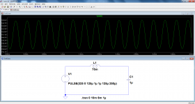
On my prototype, the leakage inductance referred to the primary is 75mH.In the real circuit, how much switching ripple is unintentionally reflected to the primary?
Together with the 1µF input cap, it forms a second order filter having 580Hz cutoff frequency.
Below is a simulation of the worst case, at the sinewave peaks of 325V chopped by the 4KHz switching frequency.
If the mains has an impedance ~=∞, the fundamental leakage is ~10Vpp.
This looks large, but of course the mains impedance is nowhere near infinity
The problem is more subtle than it looks: what the implicit converter uses here is not the magnetizing inductance, but the leakage inductance, which depends mainly on the windings and core geometry, and very little on the core material.How high can switch frequency go before current eddies begin to fit in the laminations
of a typical transformer built for 60Hz?
This indicates that the laminations aren't very involved in the process.
Another way to see this is to imagine that the primary acts like a big shorted turn, shielding a good part of the iron from the HF switching.
There is something else to take into account: iron losses vary as a power of the induction, and if the voltage is kept constant, increasing the frequency from 60 to 4000Hz will reduce these losses very much.
Eddy currents are less affected by induction than other iron losses components, but overall, the effect is perfectly bearable: you can just detect that the region of the laminations just under the secondary is slightly warmer than the rest, but no more.
Attachments
- Status
- This old topic is closed. If you want to reopen this topic, contact a moderator using the "Report Post" button.
- Home
- Amplifiers
- Power Supplies
- High Voltage Variable Supply on a Shoestring