Yes with an amplified diode it is much easier. It is difficult to mount several diodes ontop of the output T's and also you can control the bias current. There's a simple rule for it: For an darlington output, the voltage over both emitter resistors should be 47mV and for a CFP output the optimum voltage over both collector resistors is about 8mV. This is impossible to achive with diodes due to the component variations in diode and transistor junctions.
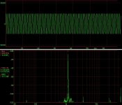
Attached is a distortion measurement of my circuit with no load. A Xonar DX soundcard and Wavespectra was used for recording. With 8R load connected, distortion quickly rises to >0.01% tough. Maybe paralleling several output T's would help here as it reduces current variations. Is it worth the trouble to try and match the output T's?
Actually I was supised to see how well the real circuit correlates to the simulation. The only thing where Spice is always far off is the distortion. This is probably because a.) it assumes ideal components with identical characteristics and b.) no parasitics are simulated such as stray inductance on the PCB.
Attachments
Yes with an amplified diode it is much easier. It is difficult to mount several diodes ontop of the output T's and also you can control the bias current. There's a simple rule for it: For an darlington output, the voltage over both emitter resistors should be 47mV and for a CFP output the optimum voltage over both collector resistors is about 8mV. This is impossible to achive with diodes due to the component variations in diode and transistor junctions.
Attached is a distortion measurement of my circuit with no load. A Xonar DX soundcard and Wavespectra was used for recording. With 8R load connected, distortion quickly rises to >0.01% tough. Maybe paralleling several output T's would help here as it reduces current variations. Is it worth the trouble to try and match the output T's?
Actually I was supised to see how well the real circuit correlates to the simulation. The only thing where Spice is always far off is the distortion. This is probably because a.) it assumes ideal components with identical characteristics and b.) no parasitics are simulated such as stray inductance on the PCB.
Try a 4R load and if the distortion rises a lot then adding more on the output may help and may make it worse depending on if you have enough current to drive them. Matching is a good idea.
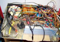
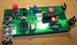
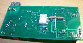
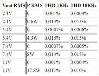
Just a little update, the amplifier is up and running now, so far I have installed three channels. This is going to be a 5.1 amplifier for my PC (mostly for gaming purpose). Theres a switch-controlled relay on each PCB to toggle between speaker and headphones output.
So far it works well, bias current is stable once the amplifier is warm.
Also attached is the THD measurement results.
Obviously the output stage is the limiting factor here.
So far it works well, bias current is stable once the amplifier is warm.
Also attached is the THD measurement results.
Obviously the output stage is the limiting factor here.
Attachments
Hi There!!
Analog device just released a new High Voltage opamp at +/- 50Vdc.
I t looks like it may work well for audio use with a 22V/us slew rate.
For those whom are interested and would want to take a look at it, here is the data sheet,
http://www.analog.com/static/imported-files/data_sheets/ADA4700-1.pdf
ADA4700-1 datasheet and product info | High Voltage, Precision Operational Amplifier | High Supply Voltage Amplifiers (>=+12V) | Analog Devices
FWIW
jer")
Analog device just released a new High Voltage opamp at +/- 50Vdc.
I t looks like it may work well for audio use with a 22V/us slew rate.
For those whom are interested and would want to take a look at it, here is the data sheet,
http://www.analog.com/static/imported-files/data_sheets/ADA4700-1.pdf
ADA4700-1 datasheet and product info | High Voltage, Precision Operational Amplifier | High Supply Voltage Amplifiers (>=+12V) | Analog Devices
FWIW
jer
Last edited:
http://cds.linear.com/docs/en/datasheet/6090fb.pdf is another new 140 V op amp
you can go floating supply output like cheap Crown/Beringer/QSC PA - then the gnded common emitter output Q can be driven from ordinary op amp V
you can go floating supply output like cheap Crown/Beringer/QSC PA - then the gnded common emitter output Q can be driven from ordinary op amp V
Analog device just released a new High Voltage opamp at +/- 50Vdc.
I t looks like it may work well for audio use with a 22V/us slew rate.
Looks very interesting - I've never seen on-chip snubber networks before. The lack of the traditional LTP input stage also appeals - indicating it may well be RF-resistant. I could only have wished for a decompensated version to be made available which would then mitigate twest's point about lowish loop gain. In the meantime keep the die at -40oC and the CM voltage near the -ve rail
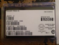
I just received two of the ADA4700-1's today!!!
It will be a while before I get to testing them as I have few other projects that I must finish up first.
When I do I will certainty post my results here.
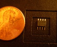
They are in a a SOIC package and that is not so bad to work with and with a fine tipped iron you could solder some 30ga. wire wrap wire pigtails to the chip if you had to.
I do have some even smaller packaged components that I am trying to figure out how to mount such as the TSSOP and such, so the SOIC package is not so bad.
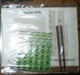
TI makes I great little adapter kit for $10 that allows you adapt 6 different package styles to 8-DIP.
It can be found here,
DIP Adapter Evaluation Module - DIP-ADAPTER-EVM - TI Tool Folder
It is a very quality board as expected from TI and comes with with gold plated pins and pads as well!!
It is a much cheaper alternative compared to some of the other adapters I have seen even if you only use the 6 X SOIC-8 partitions from the board.
Meanwhile I had developed a current buffered opamp amplifier a few months ago using a BD911/912's and it worked great except for the poor voltage swings caused by the common opamp's I was using (TL072 and LME49860).
I had just disassemabled it from my proto board only days before I saw the recent release of this chip.
But I did package all of the components I used separately so the they wouldn't get lost.
I will be employing the ADA4700-1 in the very same circuit as a test and see how it does.
I will start with the lower volatges at +15v and -/+15V and work my way up from there.
I do have a +/- 26V supply but any higher than that I will have to build a new supply.
So, it will be interesting to see how this chip and design will work.
If this chip works well it will be a very simple and decent little power amplifier for cheap!!
It worked well with the common opamp's except for the limited voltage swing.
Cheers!!!
jer
It will be a while before I get to testing them as I have few other projects that I must finish up first.
When I do I will certainty post my results here.
They are in a a SOIC package and that is not so bad to work with and with a fine tipped iron you could solder some 30ga. wire wrap wire pigtails to the chip if you had to.
I do have some even smaller packaged components that I am trying to figure out how to mount such as the TSSOP and such, so the SOIC package is not so bad.
TI makes I great little adapter kit for $10 that allows you adapt 6 different package styles to 8-DIP.
It can be found here,
DIP Adapter Evaluation Module - DIP-ADAPTER-EVM - TI Tool Folder
It is a very quality board as expected from TI and comes with with gold plated pins and pads as well!!
It is a much cheaper alternative compared to some of the other adapters I have seen even if you only use the 6 X SOIC-8 partitions from the board.
Meanwhile I had developed a current buffered opamp amplifier a few months ago using a BD911/912's and it worked great except for the poor voltage swings caused by the common opamp's I was using (TL072 and LME49860).
I had just disassemabled it from my proto board only days before I saw the recent release of this chip.
But I did package all of the components I used separately so the they wouldn't get lost.
I will be employing the ADA4700-1 in the very same circuit as a test and see how it does.
I will start with the lower volatges at +15v and -/+15V and work my way up from there.
I do have a +/- 26V supply but any higher than that I will have to build a new supply.
So, it will be interesting to see how this chip and design will work.
If this chip works well it will be a very simple and decent little power amplifier for cheap!!
It worked well with the common opamp's except for the limited voltage swing.
Cheers!!!
jer
Attachments
Last edited:
They are in a a SOIC package and that is not so bad to work with and with a fine tipped iron you could solder some 30ga. wire wrap wire pigtails to the chip if you had to.
I've taken to mounting SOIC8 packages diagonally on 2mm pitch board like this - 2pc FR4 PCB Board Double Side KT 1058D Size 109x60x1 6mm Pitch 2 0mm Taiwan | eBay
With a bit of wire (or an 0603 0 ohm resistor) to every other pin the connections come out in a zig-zag. The spacing's not perfectly 0.05" but its near enough that this can be made to work for SO-14 pin packages too.
<<TI makes I great little adapter kit for $10 that allows you adapt 6 different package <<styles to 8-DIP.
<<It can be found here,
<< DIP Adapter Evaluation Module - DIP-ADAPTER-EVM - TI Tool Folder
Many thanks Gerald for the heads up on this adapter - I have just ordered a couple from TI. Excellent value for the money with shipping included in the item price and will solve so many prototype and DIY challenges.
http://www.ti.com/tool/dip-adapter-evm
I have had a TI account for years and often order development samples professionally, but only just now having a good look around, thanks to Gerald. Duh!
TI also offer little demo boards for the low noise, high speed 5 pin LDO regulators in SOT223 and DDPak packages for $5 ea. These will be very useful for retrofitting/upgrading old Marantz CD players for example, something I am in the middle of right now. I'll let you imagine the expletives....
http://www.ti.com/lit/ug/sbvu004/sbvu004.pdf
http://www.ti.com/lit/ug/sbvu005/sbvu005.pdf
- Status
- This old topic is closed. If you want to reopen this topic, contact a moderator using the "Report Post" button.
- Home
- Amplifiers
- Solid State
- High-voltage-opamp based amplifier