AH....
Hi,
Ah ah...I was thinking along the same lines.
A damping R in front of the bridge/diode and yet another one just after it...all that + the snubber would be effective in quenching the diodes peaks, wouldn't it?
Anyone tried this?
And would it be detremintal to the PSU internal impedance, making for a rather slow PSU?
Not that I think so...with a well designed supply it shouldn't have a negative impact, but I haven't tried it yet.
Cheers,")
Hi,
and try a similar value >after< the rectifiers but before the
Ah ah...I was thinking along the same lines.
A damping R in front of the bridge/diode and yet another one just after it...all that + the snubber would be effective in quenching the diodes peaks, wouldn't it?
Anyone tried this?
And would it be detremintal to the PSU internal impedance, making for a rather slow PSU?
Not that I think so...with a well designed supply it shouldn't have a negative impact, but I haven't tried it yet.
Cheers,
The power supply capacitance should provide a low enough
impedance if the current drain isn't too high, particularly if
there is a good regulator following it. Some experimentation
may be needed; there might be a 'sweet spot' that balances
damping and supply regulation.
I noticed some time ago that a small series resistance after
the diodes did reduce ringing by limiting the peak current
into the capacitors. A small inductance in series with the
resistor >might< reduce RFI propogation, or it might exagerbate
ringing in spite of the damping resistor. This needs some
measurement and experimentation.
A pi configuration with an inductance instead of a resistance following the damping resistor might be useful:
The whole configuration might be a small value of R, then a small
C in the form of a 1 uf film cap followed by another small R or L and finally a reasonably sized electrolytic. That in turn could be
followed by another small R or L so that a multi-pole filter would
be formed. This gets tricky because it could compromise the
desired low output impedance of the unregulated supply, but
it might just tame those noisy diodes, even a generic 1N00x
diode and squelch some power line induced noise as well.
--Damon, an electronic engineer I ain't
Re: Series resistor
I tried 3.9 Ohm but the player did not work (too much voltage drop). Then tried 2.7 Ohm with same result. Finally settled for 1.35 Ohm (two 2.7 Ohm parallel). Not much difference in sound with 0.75 Ohm though.
Hi Fred,Fred Dieckmann said:Try about 5 ohms........
I tried 3.9 Ohm but the player did not work (too much voltage drop). Then tried 2.7 Ohm with same result. Finally settled for 1.35 Ohm (two 2.7 Ohm parallel). Not much difference in sound with 0.75 Ohm though.
DIODE DAMPING.
Hi,
Elso,
Not that I want to reply in Freds' place but in some cases, as you experienced yourself, it may may be impossible to implement due to too high a voltage drop.
I feel Fred mentioned it as something you can do on your own design, not exactly as a retrofit to existing gear.
Too low a resistor value will have little effect, not that you didn't know that already.
Fred,
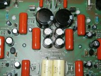
I'm in the process of upgrading my McCormack DNA .5 Deluxe amp (replacing caps and such). The amp uses the following Bridge rectifiers for the distributed power supply sections (BRUS620 - 8A)
http://www.edidiodes.com/PDF/Bridges/BRUS6.PDF
They look fairly fast (50ns) but no idea how soft they are. Any recommendations for a better replacement?
Also, if you look at the link you'll see that pins are in a straight line. Possible mplementation issue with other substitutions - thoughts?
Thanks,
bob
Brus620 - 8a
These are not specified as soft recovery. You won't find many high speed diodes in bridged packages and I have seen no soft recovery types in that package. You might want to try snubbers with the existing brides.
http://www.hagtech.com/pdf/snubber.pdf
I would be very careful about changing components in the McCormack products as Steve McCormack is about as good as they come on passive component selection and that is one of the most important factors in the sound of his amps. You could easily degrade the sound of this amp. Mr. McCormack might have some suggestions though.
Attachments
Hi Fred
What do you think about 40cpq100 and using them in Aleph 4 PS. Each rail would have one rectifier bridge built of these diodes. They are 40A 100V. Someone has been selling them and I have purchased 20 pcs. 1$ each. Any opinion.? What values would you recommend for snubbers. I have two transformers, one for each monoblock.
This is the PS schematic that will be used as base.
.PS Schematic
Thanks in advance
Trigon
Choke regulation is a great way of getting around the problem.....but "they dont even have to be that big" is a truth with modifications. If you dont want a hole lot of loss, the choke have to be pretty sturdy. I made a set of 2.2mH air cores...they are like 1.5 kilogram each 
Magura
Magura
Below are two sims. The first one the current through the transformer using an ordinary bridge/capacitor network (5 Ohm resistor at 10V p-p from the transformer seconary). The peak currents through the diodes is over 10A.
The second graph is the current through the transformer using a 2.7mH inductor in series with the bridge and before the capacitor. The peak currents through the diodes are now under 2A. This is a 1:5 reduction of peak currents by adding a small choke.
(1) The diodes don't shock-excite the RLC tank circuit, because the choke damps the response.
(2) The peak currents in the diodes are lower.
(3) The peak currents in the transformer are lower. This reduces heat dissipation in the transformer, and reduces the magnitude of the transformer's magnetic field.
Attachments
1-2 mH at 2-3A can be a pretty small choke. Any losses in the choke is easily made up with the reduced peak currents in the transformer and diodes. In addition, the ripple current in the filter capacitor is much smaller.
Digikey has a 5.6mH, 2.0A, 1.14 Ohm choke for $10. It is 1" diameter and 1" tall (from JW Miller series 1140). There's lots of other chokes in the same series up to 15mH.
They also have toroid chokes (1mH, 2.4A, 0.30 Ohms) for less than $5 (JW Miller series 2300).
Chokes are cheap and easy....
Digikey has a 5.6mH, 2.0A, 1.14 Ohm choke for $10. It is 1" diameter and 1" tall (from JW Miller series 1140). There's lots of other chokes in the same series up to 15mH.
They also have toroid chokes (1mH, 2.4A, 0.30 Ohms) for less than $5 (JW Miller series 2300).
Chokes are cheap and easy....
Kashmire said:Instead of worrying about high-speed diodes, why not use choke regulation?
because it would look very low tech and unsophisticated.
The problem you have when you run the choke directly after the bridge is that your DC rail voltage is now ~0.9 X the secondary AC voltage instead of ~1.3X (under load in both cases).Kashmire said:1-2 mH at 2-3A can be a pretty small choke. Any losses in the choke is easily made up with the reduced peak currents in the transformer and diodes. In addition, the ripple current in the filter capacitor is much smaller.
Kashmire said:Below are two sims. The first one the current through the transformer using an ordinary bridge/capacitor network (5 Ohm resistor at 10V p-p from the transformer seconary). The peak currents through the diodes is over 10A.
The second graph is the current through the transformer using a 2.7mH inductor in series with the bridge and before the capacitor. The peak currents through the diodes are now under 2A. This is a 1:5 reduction of peak currents by adding a small choke.
(1) The diodes don't shock-excite the RLC tank circuit, because the choke damps the response.
(2) The peak currents in the diodes are lower.
(3) The peak currents in the transformer are lower. This reduces heat dissipation in the transformer, and reduces the magnitude of the transformer's magnetic field.
Kashmire,
The choke in series don't address the issue with the diodes trr and it's high frequency energy related to it, what you achieve is just better PFC.
And in general when talking about chokes, if a common mode choke is used then the current is cancelled out by the two windings and can easily be 30 mH specified for couple of amperes and the component weight(size) is still around some hundred grams.
It's a different thing when using a single winding choke, they will certainly get big.
Choke Input or PI-Filter choke
Hi,
Please be aware there is a big difference between a choke input power supply, as used by Cello, and a Pi-filter, as used in some Pass amplifiers.
For the choke input filter you need a huge choke of a rather high value and for the a PI-filter a 2.2mH choke will be sufficient.
In the Cello Power amp the choke was as large as the transformer!
Also there is a minimum value for the choke in the choke input powersupply.
I am inclined to use the latter for a class A amplifier and the Pi-filter for a Class AB. See also:
http://java.audioasylum.com/cgi/m.pl?forum=tweaks&n=36470&highlight=elso+choke&r=&session=
The choke in series don't address the issue with the diodes trr and it's high frequency energy related to it, what you achieve is just better PFC.
There's more than one thing happening, but from a common root cause. A diode can cause HF noise because the diode commutates at a very high peak current. A choke forces the diode to commutate at zero current (at both turn-on and turn-off), so the diode isn't "slamming" the current when it turns on.
The problem you have when you run the choke directly after the bridge is that your DC rail voltage is now ~0.9 X the secondary AC voltage instead of ~1.3X (under load in both cases).
It's not a problem, if you select the transformer voltage properly. It is a problem if you are trying to retrofit an old circuit.
Kashmire said:
There's more than one thing happening, but from a common root cause. A diode can cause HF noise because the diode commutates at a very high peak current. A choke forces the diode to commutate at zero current (at both turn-on and turn-off), so the diode isn't "slamming" the current when it turns on.
I guess it is the schematic in the post 168 you simulated?!
I'm a bit unsure what you have in series with the capacitors but anyhow...
If you are able to change/build a SPICE model (or whatever you use) then make a perfect diode with non of it's backdraw and make your both simulation again and tell me your results, ok?
TNT said:Welcome to the forum !
Ultima Thule - interesting avatar - what does it mean ?
/j
Thanks!
Ultima Thule; the antique name for the "unknown" land, the most northern part of europe (Nordic) told by Vergilius and other Roman authors.
roddyama said:
The problem you have when you run the choke directly after the bridge is that your DC rail voltage is now ~0.9 X the secondary AC voltage instead of ~1.3X (under load in both cases).
Kashmire said:
It's not a problem, if you select the transformer voltage properly. It is a problem if you are trying to retrofit an old circuit.
Be careful though, during the first few cycles after switch on, the capacitor will be charged up to the normal 1.3 .. 1.4 x Urms. Only then the choke will start becoming effective and the voltage decreases to 0.9 x Urms. Also with no/low load the voltage goes up again. So the circuit should be able to cope with the higher voltage, just as the capacitor. You cannot design for 0.9 x Urms as the working voltage of the supply capacitor.
Ultima Thule said:
And in general when talking about chokes, if a common mode choke is used then the current is cancelled out by the two windings and can easily be 30 mH specified for couple of amperes and the component weight (size) is still around some hundred grams.
It's a different thing when using a single winding choke, they will certainly get big.
Are you sure that a common mode choke will be effective here as an input choke? The load is not common mode, but differential mode. Because you want to store magnetic field-energy in the core you want the fields to add and not cancel. So, if the currents cancel no energy is stored.
Steven
- Status
- This old topic is closed. If you want to reopen this topic, contact a moderator using the "Report Post" button.
- Home
- Design & Build
- Parts
- High Speed Diodes