I must be getting soft in my old age
'It also makes me wonder, that some people standarise on a certain part without without even trying to listen.'
This may not be quite the case because I don't think too many people realize what the important specs are!
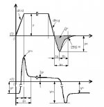
It used to be that people assume that shottky diodes were the thing to use because of their fast forward turn on times and lack of reverse recovery effects. The IR Hexfreds were very popular because of it's high voltage and current ratings and short recovery time. This fast recovery diodes are optimized for switching power supplies that switch at 50KHz to 200KHz. Fast recovery times minimize power losses at these switching frequencies. Increasing demand for low EMI from electronics has led to the development of soft recovery diodes where not only the reverse recovery time tRR ( t subscript rr) but the ratio of the over the tB over tA, where tRR = tA+tB determine define the softness of the recovery current. Large ratios of tB/tA generate less noise and ringing. Many fast recovery diodes designed for soft recovery are starting include numbers for tA and tB in there data sheets. It may be that this ratio indicating softness is more important than just low tRR for the best sounding diodes
for audio power supplies. The use of snubber networks with the fast recovery diodes may allow the use of diodes that are less soft (lower tB/tA) to sound as good as unsnubbered soft recovery diodes. It may be that even soft recovery diodes can benefit sonically from the addition of snubber circuits. The fast recovery diodes designed for soft recovery are relatively new and I don't think few people have done any listening test on these diode types. I also don't think many people have experimented with listening to snubber circuits. I have achieved very good results with snubbers on fast recovery diodes designed 17 years ago that probably do not have near as good soft recovery characteristics as many of the new fast recovery diodes.
As a example of a soft recovery diode with these parameters specified:
http://parametric.fairchildsemi.com/datasheet.asp?PN=ISL9K860P3&FAM=Rectifier
'It also makes me wonder, that some people standarise on a certain part without without even trying to listen.'
This may not be quite the case because I don't think too many people realize what the important specs are!
It used to be that people assume that shottky diodes were the thing to use because of their fast forward turn on times and lack of reverse recovery effects. The IR Hexfreds were very popular because of it's high voltage and current ratings and short recovery time. This fast recovery diodes are optimized for switching power supplies that switch at 50KHz to 200KHz. Fast recovery times minimize power losses at these switching frequencies. Increasing demand for low EMI from electronics has led to the development of soft recovery diodes where not only the reverse recovery time tRR ( t subscript rr) but the ratio of the over the tB over tA, where tRR = tA+tB determine define the softness of the recovery current. Large ratios of tB/tA generate less noise and ringing. Many fast recovery diodes designed for soft recovery are starting include numbers for tA and tB in there data sheets. It may be that this ratio indicating softness is more important than just low tRR for the best sounding diodes
for audio power supplies. The use of snubber networks with the fast recovery diodes may allow the use of diodes that are less soft (lower tB/tA) to sound as good as unsnubbered soft recovery diodes. It may be that even soft recovery diodes can benefit sonically from the addition of snubber circuits. The fast recovery diodes designed for soft recovery are relatively new and I don't think few people have done any listening test on these diode types. I also don't think many people have experimented with listening to snubber circuits. I have achieved very good results with snubbers on fast recovery diodes designed 17 years ago that probably do not have near as good soft recovery characteristics as many of the new fast recovery diodes.
As a example of a soft recovery diode with these parameters specified:
http://parametric.fairchildsemi.com/datasheet.asp?PN=ISL9K860P3&FAM=Rectifier
Attachments
A "cap input" is a power supply in which the rectifiers are followed, downstream
This is not what I meant at all...... I was refering to putting a cap in series with the primary winding of the transformer to keep DC out of the transformer. This has been discussed on the forum before and maybe someone can find the thread in which it was described. Remember mains voltages can be letal and proceed at your own risk and use extreme caution working with these voltages.
This is not what I meant at all...... I was refering to putting a cap in series with the primary winding of the transformer to keep DC out of the transformer. This has been discussed on the forum before and maybe someone can find the thread in which it was described. Remember mains voltages can be letal and proceed at your own risk and use extreme caution working with these voltages.
tubesguy
Is that all? The way it was referred to in another thread made me think it was built into a new kind of transformer. Thanks for your reply.A "cap input" is a power supply in which the rectifiers are followed, downstream as it were, by capacitors of sufficient size as to cause the voltage to rise to its max value, depending on which rectifier scheme is being employed.
Re: A "cap input" is a power supply in which the rectifiers are followed, d
Fred,
what kind of cap do you propose for that? It will have to allow for a great deal of AC current through without heating and exploding so high power, low ESR...I haven't seen much in my life, granted, but I definitely never seen a cap in series anywhere. I don't know, but I can just see little MKP caps blowing up all over the continental US tonite")
As soon as can afford a house I plan to go on ebay, buy a 10kVA 1:1 trafo, put that in the basement and run huge 2 gauge lines to various strategic places in the house. That ought to get rid of most DC on the line.
Fred Dieckmann said:This is not what I meant at all...... I was refering to putting a cap in series with the primary winding of the transformer to keep DC out of the transformer. This has been discussed on the forum before and maybe someone can find the thread in which it was described. Remember mains voltages can be letal and proceed at your own risk and use extreme caution working with these voltages.
Fred,
what kind of cap do you propose for that? It will have to allow for a great deal of AC current through without heating and exploding so high power, low ESR...I haven't seen much in my life, granted, but I definitely never seen a cap in series anywhere. I don't know, but I can just see little MKP caps blowing up all over the continental US tonite
As soon as can afford a house I plan to go on ebay, buy a 10kVA 1:1 trafo, put that in the basement and run huge 2 gauge lines to various strategic places in the house. That ought to get rid of most DC on the line.
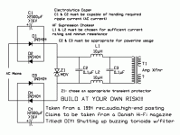
Could it be this schematic from that thread http://www.diyaudio.com/forums/showthread.php?threadid=2080
Recently I tried 1.5kVA Plitron low noise transformer (the best and most expensive they make in this range at $600) as an isolation transformer with balanced power output (2 x 60V DC with common ground). It sounded worse than my regular 30A line with front end equipment, so I didn't investigate it any further.
Recently I tried 1.5kVA Plitron low noise transformer (the best and most expensive they make in this range at $600) as an isolation transformer with balanced power output (2 x 60V DC with common ground). It sounded worse than my regular 30A line with front end equipment, so I didn't investigate it any further.
Attachments
tubesguy
I'm afraid that I must rescind my thanks.
Fred Dieckmann
Thanks for the clarification. I guess that a transformer could be bought with this "cap input" so I'm glad I asked. Also, you didn't mention which transformer specs are the most important to look up when choosing for audio. Will this choice be different if one was going to build an amp with bias as opposed to a chip amp that works strictly Class B?
re: the DC blocking filter schematic
Thanks Peter for posting the link and pic.
There's an error that i never posted the correction for: the line about C1 & C2 handling ripple current should actually read "C1 & C4 ..."
Sorry,
mlloyd1
Thanks Peter for posting the link and pic.
There's an error that i never posted the correction for: the line about C1 & C2 handling ripple current should actually read "C1 & C4 ..."
Sorry,
mlloyd1
Peter Daniel said:Could it be this schematic from that thread http://www.diyaudio.com/forums/showthread.php?threadid=2080 ...
Referring to the above diagram, what is the Z1MOV and what does it do?
Peter, I am thinking about a huge isolation transformer preferably get all three phases in the house. Correctly balance the load in the house. Not to worry, my dad is an electrician. I have been wiring circuit breakers since my early teens.
Since it seems you can hear all kinds of differences in sound how does the stereo sound when the washing machine is operating in the basement?
Mov
Hi,
From what I understand just a Metal Oxide Varistor.
What does it do? It attempts to limit inrush current and it also snubbs up crap from diodes,switches, to some extent.
I always try to use one, things sound better that way...
Cheers,
Hi,
Referring to the above diagram, what is the Z1MOV and what does it do?
From what I understand just a Metal Oxide Varistor.
What does it do? It attempts to limit inrush current and it also snubbs up crap from diodes,switches, to some extent.
I always try to use one, things sound better that way...
Cheers,
I did the wiring in my house myself and most of the appliances and fixtures have their separate lines and circuits. I have no interferences whatsoever. The only noise from washing machne is mechanical noise. I have 3 separate, dedicated lines to my systems, each line rated 30 A and containing both fases, separate for front end, separate for right channel amps and sep. for left channel amps. It's been like that for many years, but what I remeber it was a big improvement I listened to it first time, mostly in a bass region.
I also have a utility transformer on a pole, right beside my house on the street, and I hope this is bringing some improvement as well.
I also have a utility transformer on a pole, right beside my house on the street, and I hope this is bringing some improvement as well.
MVO...
MOV is Metal Oxide Varistor...it works as a bidirectional zener...they exist in various voltages...
The voltage rating is the voltage at they begin conducting and they clamp the voltage at this value...
Regards
Referring to the above diagram, what is the Z1MOV and what does it do?
MOV is Metal Oxide Varistor...it works as a bidirectional zener...they exist in various voltages...
The voltage rating is the voltage at they begin conducting and they clamp the voltage at this value...
Regards
POLES.
Hi,
How convenient.
Cheers,
/Try to bring the street into the house?
Hi,
I also have a utility transformer on a pole, right beside my house on the street, and I hope this is bringing some improvement as well.
How convenient.
Cheers,
/Try to bring the street into the house?
I remeber some people commenting on the AC power cords. They claimed that one would also have to change all the wires down to the power plant in order to see real improvement. In my case it would be maybe only 30 ft. One day I might go for that, after making arrangements with my hydro company.
Off Topic.
Hi,
My POV on that is that continuity is important...solid core in the walls, solid core powercords I use. It makes for an an amazingly cheap difference.
Some shield them but I don't see a benefit in that...I'd rather shield my speaker cables instead...reluctantly.
Cheers,
Hi,
I remeber some people commenting on the AC power cords.
My POV on that is that continuity is important...solid core in the walls, solid core powercords I use. It makes for an an amazingly cheap difference.
Some shield them but I don't see a benefit in that...I'd rather shield my speaker cables instead...reluctantly.
Cheers,
The varistor would do more good after the chokes which act as impedance limiters. The way the varistors is wired it would have to absorb all of a surge and better do it quickly (varistors are not as fast as good caps, their advantage is the nonlinear resistance). The chokes would limit the slopes of a surge, and whatever gets through is shared between chokes and varistor -> much better supression!
MOVs
MOVs
http://www.chipcenter.com/eexpert/akruger/akruger032.html
http://www.littelfuse.com/ASP/Search/Detail.asp?ID=268
Line cords :
Yes they sound different. The wiring in house walls usually in a metal conduit and is connected to the outlets with very substantial screw terminals. The line cord is suspended in space for party of its run and connected to the outlet by an often loose plug/receptical and to the amp by an IEC connector of equally poor quality. Contact materials are usually low grade brass and receive no attention to cleaning or contact enhancement products
that other contacts in the system do. Vibration in this cord will often modulate the contact resistance and develope very low level arcing that can create RF noise. This is a truly awful contact
interface carrying large currents and voltages. Just replacing your wall outlets with new ones that have cleaner and tighter contacts
can be a very worthwhile sonic upgrade. I have heard several of the audiophile line cords sound pretty different and have been building my own for ten years. The best ones pay close attention to mechanical damping. Very good speaker wire often makes poor AC cords for some reason. My favorites use wide thin copper foil and polypropylene tape. They are very light flexible and mechanically well damped. The plugs and IEC connectors are silver soldered and mechanically damped.
I seem to remember seeing respected forum member Jonathan Carr polishing the hell out of the plugs on some AC line cords in Stereophile a while back.....
Attachments
Re: I must be getting soft in my old age
Can you explain why a large tB/tA indicates softness? Intuitively, I assume we should worry about the total energy in the spike, i.e. its integrated area. Then secondly, we should worry about the slopes of the spike. There I'd guess the leading edge is as troublesome as the trailing edge. One way to bring both down might be to add series resistance at the expense of efficiency.
I wonder if all the reported sonic differences between diodes still matter if proper filtering is done, e.g. PI filtering with resistors between rectifier and first set of filter electrolytics and common mode choke between first and second set of electrolytics.
Greetings,
Eric
Fred Dieckmann said:Large ratios of tB/tA generate less noise and ringing.
Can you explain why a large tB/tA indicates softness? Intuitively, I assume we should worry about the total energy in the spike, i.e. its integrated area. Then secondly, we should worry about the slopes of the spike. There I'd guess the leading edge is as troublesome as the trailing edge. One way to bring both down might be to add series resistance at the expense of efficiency.
I wonder if all the reported sonic differences between diodes still matter if proper filtering is done, e.g. PI filtering with resistors between rectifier and first set of filter electrolytics and common mode choke between first and second set of electrolytics.
Greetings,
Eric
tRR noise
Actually the slope of the tB portion of the reverse recovery is important. I think the the longer tB times may be a smaller slope ie. a slower fall time. The design emphasis on soft recovery seems to be fairly recent and the tB/tA ration is described on relatively few part's data sheets. The increasingly strict regulatory enviroment for EMI compliance both here and in Europe
will lead to more information on and parts choices for fast recovery diode designed for soft recovery. Filtering noise in the supply is a good idea but a lots of RF gets through filters from paths like winding capacitances in chokes and transformers. EMI suppresion can be very difficult to measure and even more difficult to implement. Snubbers still seem like the best bet for RF noise reduction.
Look at the app notes at:
http://www.irf.com/technical-info/appnotes.htm
AN-989 The HEXFRED Ultrafast Diode in Power Switching Circuits
http://www.irf.com/technical-info/appnotes/an-989.pdf
at:
http://www.irf.com/technical-info/anarchive.html
2000A Optimized Ultrafast Diodes for Switching Applications
http://www.ixys.com/t03232ka.pdf
Characteristics and Applications of Fast Recovery Epitaxial Diodes
http://www.ixys.com/t052599a.pdf
at:
http://www.ixys.com/tecnot01.html
- Status
- This old topic is closed. If you want to reopen this topic, contact a moderator using the "Report Post" button.
- Home
- Design & Build
- Parts
- High Speed Diodes