Michael Koster said:- High power, high fidelity audio amplifier using transmitting tubes
- Beam tetrode push-pull output in class AB2 with local plate-grid feedback (O.H. Schade style)
- 2 stage DC driver in class A2 "zero bias" with parafeed transformer coupling to output stage
- MOSFET active anode loads and grid drive buffers to enable linear operation in A2/AB2
- Reasonable power efficiency to allow operation from a single 120 volt AC circuit < 1500W max
- Stable operating points and rated for CCS
Seems way too overcomplex ! What are you trying to do and why are you considering this approach ? What is the 'problem' this amp design is supposed to be fixing ? If you're using horns you simply will never need more than a watt or two . Driving a transformer with a 3C24 does not seem like a good idea , a push pull IT will need a serious amount of henries for best results . I'd suggest going for class A1 throughout , going A2 in the driver department means driving the driver with a low impedence . I'd suggest before committing and cutting chassis holes , to breadboard , maybe a stage at a time due to the high cost of the transformers used . I've gone down this road before with complex amp designs and binned all of them prior to completion , usually after spending huge amounts of cash on parts since left unused and huge amounts of time wasted planning chassis layout , cutting holes etc etc . A stacked Loftin-White style DC coupled 4-65A SE running at 700V with 3C24 driver will get you where you want to go with power to spare and sound good (I know this as I've built one!) . Just my 2p worth , sorry to rain on your parade
")
cheers
316A
316A,
I think you missed that this is an outdoor and mid-sized venue system, not a small room home system.
It is complex, at least to my eyes, but that doesn't mean it is compromised. If it were me doing a tube amp for venues, I'd probably do a PPP KT88 design, but this will be something totally of a different nature.
JoshK said:316A,
I think you missed that this is an outdoor and mid-sized venue system, not a small room home system.
It is complex, at least to my eyes, but that doesn't mean it is compromised. If it were me doing a tube amp for venues, I'd probably do a PPP KT88 design, but this will be something totally of a different nature.
That IT after the 3C24 looks like a compromise
For a high powered amp a pair of PP pentode connected 813 should do the trick 316A
316a said:
That IT after the 3C24 looks like a compromise
316A
Thanks for your comments. Every parade needs a little rain to keep
the dust down! I have thought through many of the choices but
some new thinking and challenge of this direction is very helpful
and thought provoking.
I worked this design from the output stage back, with the original
motivation being a high power amp using local plate-grid feedback
and zero GNFB. The choice of 4-65A instead of parallel KT88s is mainly
for show I must admit. It would be easier and cheaper to use KT88s.
If it was just to solve a problem I could think of easier ways. I could
build the same amp with 813s, but it would consume way more filament
power, have slightly lower power sens. (lower gm), and not glow
pretty orange ;-) Could probably get 250WPC from 813s in AB2
but I'm not that greedy... lol
I wanted to use the local feedback scheme to emulate low mu
triodes in the output and to avoid the use of global NFB.
Having decided on a high power local feedback stage with high voltage
tubes, which needs a lot of drive voltage, is the main reason for
using a high mu power driver. The 6N170 IGBT splits the load in
half, which results in about the same effective impedance of a
VT-25 (4k5-ish) driving the IT. But I use a PP transformer (or even
parafeed with no gap) which gives me ~300H Lpri. So though it looks
like a SE 3C24 driving an IT, I have 4K5 Rp driving a 290H
primary. Not to worry... Now if I go with the PP driver, I have 2
drive stacks in series so it's 9K into 290H. That may be a bit of a
compromise but Lundahl specifies a 15K source impedance for
the LL1660S/PP. That's (omega*L = Rsource) at 8 Hz assuming 15K
and about 5Hz assuming 9K source impedance. Of course, I need
to plot out the 3C24 load line at 20Hz with Xl around 38K to get the
whole picture. I was originally hoping to use a step-down IT but
that would take a bigger core and need a push-pull driver for sure.
Since I'm looking at AB2 for power efficiency and better linearity
than the AB1 at G2=600V (same efficiency OP) I wanted to avoid
driving grid current through the IT, therefore added the totem pole
followers with separate power supplies for grid driving. Separate
grid power supplies are used for both the 3C24 drive and the
4-65A drive for cleaner A2 operation.
The input stage is coupled to the driver grid but mot LW style
because to get 900V swing from the driver it needs to operate
in A2. Hence the fixed bias MOSFET coupling scheme. I think of
this scheme as a sort of "stacked power drive".
Operating the 801A (10Y) and the 3C24 in zero bias class A2 is also
for simplification. No bias supplies needed. A 600 ohm line driver can
easily drive the grid of a 10Y to +2.5V with 200V on the plate. I'll
be driving this with the main outputs of a mixing board.
But now that you mention it, I also have this itch to build a smaller
SET based on triode-wired 4-65As. I may even build that one first
to get my feet wet. Breadboarding is an excellent suggestion, and
I will probably work at it incrementally as suggested.
Cheers,
Michael
Michael Koster said:
But now that you mention it, I also have this itch to build a smaller
SET based on triode-wired 4-65As. I may even build that one first
to get my feet wet. Breadboarding is an excellent suggestion, and
I will probably work at it incrementally as suggested.
My learning curve with thoriated types started with the 3C24 . It's the easiest to use in terms of self-gettered spiral filament types . Others such as HK54 , 826 etc are rather nore difficult to use and the VT127A is pretty horrendous to get working . 3C24 have a nice mu of 23 and make good input stages . It is also very easy to obtain bias from the filament , just run with DC and connect the negative end to 0V and you have a 3V fixed bias supply thrown in for free
Definitely breadboard , your wallet as well as your sanity may be at stake Good luck with your project and I'll probably see you round on the AA cheers
316A (Al)
What are you trying to do and why are you considering this approach ?
I can understand the question. I got caught up in the escalating power race a few years ago with some of my 833A SE experiments. I had a single channel 200 Watt SE amplifier breadboard running for about a week. Why build a 200 watt SE amp? Sometimes it is just because you can. I paid a transformer winder a considerable sum for a custom OPT which didn't quite make it for HiFi. I abandoned the big SE amps for lack of a suitable OPT, which is still a concern for anyone contemplating such a design. Still building "the big one" is a challenge that I plan to complete some day, even though I have no practical use for a 250 WPC amp.
About a year ago there was a thread here concerning a big bunch of 807's in PPP. I was made aware of some serious P-P OPT's from Plitron that were being sold at very reasonable prices. They are rated for 400 Watts at 20 Hz 1250 ohms. I got a pair for eventual use in "the big one."
I'd probably do a PPP KT88 design....It would be easier and cheaper to use KT88s.
In this case, and in my case the choice of output tubes is restricted by the OPT's that are already chosen. With an 8K ohm primary a P-P pair of KT88's isn't going to make 250 WPC unless the plate voltage spec is ignored. With my OPT 6 or 8 KT88's is the conventional choice. I tend to avoid conventional choices. I have several transmitting tubes that I would like to use, 813's 211's, 833A's and 828's just to name a few. They would all like a higher impedance OPT though.
I'd suggest before committing and cutting chassis holes , to breadboard , maybe a stage at a time due to the high cost of the transformers used .
Trust me, with an amp of this power level this is not a suggestion, it is a requirement! There are far too many details that will get overlooked that will cause anything from subtle distortion to an offering to the fire gods.
I have had the monster OPT's for about a year. During that time I have breadboarded 3 different driver circuits, and about a dozen different output stages in every configuration from conventional (6 X KT88) to wild (Parallel cascode cathode follower). These experiments have allowed me to understand the true power supply and drive requirements of this beast, chase down some little distortion issues, and rule out a bunch of different designs. I have still not settled on a final design, but most of the early front runners have been eliminated because I have discovered just how sensitive these toroidal OPT's are to DC imbalance.
When designing a conventional (of reasonable power) amplifier, I usually start with the output stage, simulate, calculate, and finally breadboard. I steal drive from some other amp that I have around and test with bench supplies. When building "the big one" that is not possible. 1200 volt bench supplies don't come from Walmart and 300 V P-P of drive can't be lifted from that EL84 amp on the bench. All of the subcircuits need to be designed and tested individually before anything can be "built." I find that it is easiest to start with the driver, since it usually can be tested with a bench supply.
Now where would I find a worthy power transformer and chokes? I could wire the secondaries of three 480V/1A control transformers in series and use a bridge rectifier...
My 845SE amplifier used a single 480 volt 500 VA control transformer. It feeds a vacuum tube voltage doubler (2 X 5AR4). I get 1050 volts at 200 mA. You would probably get about 1100 volts with SS rectifiers. 600 volt (or 575 volt) control transformers exist, but are not as common as 480. I have obtained 2 rated at 500 VA cheap on Ebay. The big Antek toroids found on Ebay are another possibility. I also scored a couple of monster 1 KW+ linear amplifier transformers on Ebay over the past few years (one from another forum member), but they tend to be closer to 2 KV.
The "big one" is not a high priority, but it is being used in the design of a "universal P-P driver" board. Driving KT88's is easy. Driving transmitting tubes, more difficult. Designing a driver that can handle this and do screen driven sweep tubes or huge cathode followers is well, a bit of a challenge. Why? If it was easy everyone would do it. I am glad to see a few posters on this forum that strive to do something different. I already have enough 300B and KT88 amps.
Thanks Al and George,
There's a lot of valuable insight in your writing.
I have a number of new (to me) things here and I'll definitely heed the
voice of experience and take them one or two at a time on the
breadboard. Tantalum anodes, AB2 with local feedback, SMPS for
filaments, etc.
I'll start with the 3C24 and work out from there since I'm looking
for 900V P-P drive or more. Maybe a small TT amp will happen first.
Michael
PS
Al, so you got the bit about the trolley;-) I think 12U should do it.
I kind of couldn't pass up the OPTs as they were used in an amp with
similar operating conditions as I'm considering. Also they're iron...
Big iron... Like that, eh? a bigga irona boombada boombada...
Attachments
Michael Koster said:I have a number of new (to me) things here and I'll definitely heed the
voice of experience and take them one or two at a time on the
breadboard. Tantalum anodes, AB2 with local feedback, SMPS for
filaments, etc.
PS
Al, so you got the bit about the trolley;-) I think 12U should do it.
Definitely get some experiments on the go
If this amp of yours is going to be moved around , you'll need to think about either removing the valves , thoriated types are particularly fragile in this regard . Funny you mention a trolley , I do my breadboards on a chopped-up Tek 485 scope trolley . The top section which tilts has been sawn off and used as a lower shelf . 316A
thoriated transmitting tubes
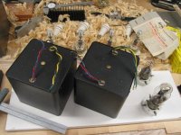
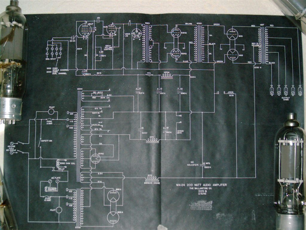
look for some Ballantyne MX-24's:
look for some Ballantyne MX-24's:
An externally hosted image should be here but it was not working when we last tested it.
Yeah, that's nice construction and similar to what I have in mind
only 19" rack based. Love that wrinkle paint. That looks like a nice
recap job. What do these sound like? Are you using them full range?
Is the third can on the bottom level an oil cap?
cool...
Michael
I guess these are rated at 200 Watts. That looks like about a 1500VA
power transformer for each channel, a little bigger than I would expect.
I guess that's an honest CCS rating, convection cooled. Imagine these
in a metal shed at a drive-in in Alabama in July, 100 F and 100%
humidity. Must've been a bug zapper in it's own right;-)
316a said:
Definitely get some experiments on the go
316A
I'll start with an anode bake-off to see how many good tubes I
have. Then I'll be ready to cobble together a prototype drive stage.
Oh there's the matter of the 1200V power supply. I need to convert
my bench supply to a doubler. It's based on a 480V/500VA control
transformer that should be provide power to bring up one channel
at 1/2 output. That's still a while off though...
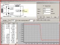
I think the doubler looks like a really good approach for a B+ supply
for this thing. It needs to supply 1200V at from 250mA up to 680mA at
full output. PSUD simulations look encouraging, just need to get a
control transformer that will handle 8A peaks at 480V. Probably will
take about 1.5 KVA, maybe up to 2 KVA .
There's one drawback to the whole plan. It may need a padded tube
caddy to go with it if I plan to actually move it around. I think that's
going to be OK since it's truly an amp for special occasions.
Cheers,
Michael
Attachments
I'll start with an anode bake-off to see how many good tubes I have.
I found 3 X 4-65A's in my collection. I decided to "test" them in SE back when I was uning 6AV5's for light bulbs. Unfortunately all 3 turned out to be bad. Two were obvious as soon as filament voltage was applied. White smoke filled the inside of the tube (gone to air). The third was so gassy that it glowed blue with 200 volts of B+. They were all "Penta" branded. I have yet to find a Penta tube that I like.
I'm looking for 900V P-P drive or more.
And I thought I needed a bunch of drive.
tubelab.com said:
I found 3 X 4-65A's in my collection. I decided to "test" them in SE back when I was uning 6AV5's for light bulbs. Unfortunately all 3 turned out to be bad. Two were obvious as soon as filament voltage was applied. White smoke filled the inside of the tube (gone to air). The third was so gassy that it glowed blue with 200 volts of B+. They were all "Penta" branded. I have yet to find a Penta tube that I like.
And I thought I needed a bunch of drive.
I have 2 Penta brand that also say Raytheon on them. I'll report the
results. I also have some RCA and some Eimac. The 3C24s are all metal
base Eimacs.
I'm using high voltage drive because I want to use local feedback
to improve damping factor, which decreases the power sensitivity of
the output stage. I'll have the equivalent of a mu~4, Rp~1000
triode stage, and with 900Vpk plate swing per side that's 225Vpk
on each grid. Grid-to-grid that's 900Vpk-pk
Another way around the power sensitivity problem is parallel output
tubes, which is bound to have it's own set of issues. I guess driving
~300 ohms Zpri is a challenge, even with parallel KT88s.
I identified a power transformer that might deal with 8 amp charging
spikes from the doubler; the Signal SU-2:
http://www.signaltransformer.com/Data/Datasheets/DU-SU.pdf
only weighs 54 lb.
Michael
And I thought my latest purchase 10H 300mA chokes were a little
excessive in the mass dept... All this iron I've collected to do this
one simple job is getting rediculous.
I got this pair of 814 transmitter tubes been wanting for a purpose.
But I think with g1=g2 drive they might not need the full 1200V on
the plate to get moving. Above 600V quiescent, I'm not quite ready
to play in that league.
Suppose same the difference between falling from 6 stories or 12.
Then again, stories don't reach out to grab you unawares either....
I've got a Hi-Pot tester w Variac that goes more than 5000VAC.
To be perfectly honest, I'm so afraid of that box, I've never even
dared to turn it on...
only weighs 54 lb..... And I thought my latest purchase 10H 300mA chokes were a little excessive in the mass dept...
I spotted some 2HY 1.5 AMP chokes in a surplus shop. I brought 3 of them home, thought they were heavy when I put them in the car. I was thinking SE OTL, so I set two of the chokes and a 500VA isolation transformers on a chassis, and the chassis bent. Total iron weight.... 100 pounds. The OTL is on hold (as all of my tube projects now) because.... reality set in. With an idle current of 1.5 amps I need 4 6336A tubes per channel, and I still only get about 10 watts. Maybe an OPT isn't such a bad idea. They are much lighter than those chokes, and I can get 30 watts out of one 6336A in cathode follower mode.
I identified a power transformer that might deal with 8 amp charging spikes from the doubler
I built a variable power supply that used a variac and a 1KVA control transformer with a bridge rectifier and a BFC (1200 uF 450 V) on each 240 volt secondary (circlotron experiments). The charging current for the BFC caused a 15 amp slow blow fuse to instantly evaporate on power up.
The fix. Inrush current limiters (4 of them in parallel). These things are a thermistor that is made for use in series with the power line. Their resistance is high (tens of ohms) when cold, but the current flowing through them raises their temperature causing the resistance to drop (tenths of an ohm). They come in several sizes. On a supply like this some experimentation is required to find the right one. I had only two sizes here (CL-70 and CL-90), hence the 4 in parallel.
This still doesn't help the fact that the conduction angle for SS diodes is narrow and a choke input doubler is kinda hard to do.
Keep in mind that most industrial control transformers are inefficient and run hot.
Don't 814s have a very low G2 rating? ... But I think with g1=g2 drive they might not need the full 1200V
If G1=G2 drive can be made to work the voltage on G1=G2 is fairly low. I have experimented (somewhat unsuccesfully) on some sweep tubes and find that the idle voltage is low (+10 to +30 volts) and only a few volts of drive is needed. Some transmitting tubes were actually specified for G1=G2 drive. This was intended for AM modulator use where distortion was not a serious issue.
tubelab.com said:
I spotted some 2HY 1.5 AMP chokes in a surplus shop. I brought 3 of them home, thought they were heavy when I put them in the car. I was thinking SE OTL, so I set two of the chokes and a 500VA isolation transformers on a chassis, and the chassis bent. Total iron weight.... 100 pounds. The OTL is on hold (as all of my tube projects now) because.... reality set in. With an idle current of 1.5 amps I need 4 6336A tubes per channel, and I still only get about 10 watts. Maybe an OPT isn't such a bad idea. They are much lighter than those chokes, and I can get 30 watts out of one 6336A in cathode follower mode.
My latest build had at least 100lbs of Iron. The 17X10X3 Black Hammond Steel chassis didn't flex or bend, even when supporting the weight on 4 little rubber feet at the corners. If you havent already I'd give them a try.
I've held onto an old PC chassis just for that very purpose.
Build something out of or into it. Needing to be bulletproof.
I'm a terrible packrat, just can't trow away stuff that might
be useful 10 or twenty years down the road...
And I do mean PC, not AT, not ATX... Steel. Thick. Heavy.
It held some sort of external extension backplane for XT.
The power supply inside was LINEAR, believe it or not.
And the chassis very much build to handle the weight of
the huge low voltage transformer. Might be good for DC
filaments if it still works???
Externally, it doesn't look much like anything out of the
ordinary. Its only when you try to lift it!
I'm fairly sure I can fit all my Edcor, Hammond, and Antek
transformers and Chokes. Hundred pounds or thereabouts
sounds about right.
Constructing the power section has been holding me back
for much too long. But I got overkill chokes now. And they
opened a new Harbor Freight nearby, where I found tools
for making nice round holes in 10gauge steel. I can't think
of anything else I might need still lacking.
Though I got only one pair of 814's, with sockets and caps.
May lame out and default to 6L6's or 6GT5A compactrons.
I have those types in sufficient quantity for both channels.
The other tubes I have in quantity, are 6CU5 and 6DJ8.
Expect to see them figured in somewhere.
And I have that X100 Fisher thing to investigate 7189s.
That project has been held up, but not forgotten. As I've
had to spend my evenings fixing my broken truck instead.
But the truck just passed inspection, I'm done with that
distraction hopefully long enough to get something real
done with all this tube crap I've been collecting. Besides
simulation and measurement, show and tell, etc...
The 17X10X3 Black Hammond Steel chassis didn't flex or bend, even when supporting the weight on 4 little rubber feet at the corners.
The chassis that I used was 17X10X3 aluminum. I got it cheap at a hamfest, but it looked like a Hammond. It may have been abused in its earlier life because one of the spot welds gave way when I started piling the transformers on the top for a trial fit. I came to the conclusion that all of the parts would not fit on that size deck anyway, so If I was to build that amp it would have to be monoblocks.
I'm a terrible packrat, just can't trow away stuff that might be useful 10 or twenty years down the road...
Unfortunately I am the same way. I have been living in the same house for 30 years, it is full. I am paying rent on two rental storage units too. After having two relatives pass away recently and having to help dispose of their lifetime collections, I decided that most of my collection needs to go while I can decide what to do with it. The rent on the storage units was just increased again. It now costs me $5K per year just to keep it all. I had an estimated (by weight) 100,000 tubes a year ago. All loose, unboxed, and unsorted. I think that I eliminated about half of them last year (all of the obvious junk).
I spent the entire weekend sorting. I went through about 8 to 10 thousand tubes. About 1000 of them were 6AK5's, plenty of 6AS6, 6AL5, 0A2. Hundreds of 12AU7's, 6189 and 5693. There were a few useful tubes too. So after about 20 hours of sorting through dirty tubes, I did uncover 2 X WE 5842, and 1 TungSol 5842. I plan to keep a lifetime supply of the useful stuff, and wholsale the rest. How many is a lifetime supply of 12AU7, 10? How about 6AL5, 0!
Then I have amassed at least 1000 pounds of iron over the years........
Yep, I've only used them full range, so far...
It's a GE pyranol 10 uf 1500 VDC (660 VAC!). I'm thinking about augmenting it a bit. Or going LC(LC). It's a swinging choke input filter. Class B , pretty much. 200 watts clean, but upwards of 300 before it gets too audibly distorted. The first stage is heavily modified and there is DC on all the filaments. They sound... effortless. There is no end to the dynamics, no compression, and I've yet to build a speaker that can handle them, really. But I'm working on that...lol! The only complaint I have is a bit of mechanical trafo hum. But I've got 16.5kVA of balanced power coming along to remedy that, I hope! In all things, excess!
The large trafo is all B+ for the finals. The smaller one is everything else. They were built like the proverbial outhouse.
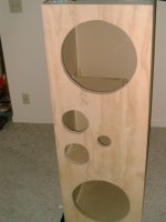
ps the big holes are 15's"
It's a GE pyranol 10 uf 1500 VDC (660 VAC!). I'm thinking about augmenting it a bit. Or going LC(LC). It's a swinging choke input filter. Class B , pretty much. 200 watts clean, but upwards of 300 before it gets too audibly distorted. The first stage is heavily modified and there is DC on all the filaments. They sound... effortless. There is no end to the dynamics, no compression, and I've yet to build a speaker that can handle them, really. But I'm working on that...lol! The only complaint I have is a bit of mechanical trafo hum. But I've got 16.5kVA of balanced power coming along to remedy that, I hope! In all things, excess!
The large trafo is all B+ for the finals. The smaller one is everything else. They were built like the proverbial outhouse.
Michael Koster said:Yeah, that's nice construction and similar to what I have in mind
only 19" rack based. Love that wrinkle paint. That looks like a nice
recap job. What do these sound like? Are you using them full range?
Is the third can on the bottom level an oil cap?
cool...
Michael
I guess these are rated at 200 Watts. That looks like about a 1500VA
power transformer for each channel, a little bigger than I would expect.
I guess that's an honest CCS rating, convection cooled. Imagine these
in a metal shed at a drive-in in Alabama in July, 100 F and 100%
humidity. Must've been a bug zapper in it's own right;-)
ps the big holes are 15's"
Attachments
- Status
- This old topic is closed. If you want to reopen this topic, contact a moderator using the "Report Post" button.
- Home
- Amplifiers
- Tubes / Valves
- High-power amplifier using transmitting tubes