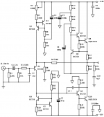
Here's a headphone amplifier designed specifically for Sennheiser HD600 headphones. It will work well with any 150+ ohm headphones.
The design is a somewhat unconventional 2 stage amplifier, it runs off unregulated supplies (12VAC), is current feedback, and uses a singleton input stage.
The input stage is linearised by two constant current sources (Q2,Q3 and Q4, Q5) drawing a current of about 2 mA through Q1. R4 allows the DC offset inherent to the single transistor input stage to be adjusted to zero. The VAS is also the output stage loaded by an SRRP style current source biased to roughly 46mA. I have not yet worked out the value of C7, perhaps it is not even necessary due to the simple nature of the amplifier. R21 and C10 form the Zobel network although I doubt that even this is actually necessary for stability. R13 and C5 prevent any supply ripple from being injected onto the output via the current source. C6 allows the current source to 'float' at AC output voltages (assuming you're not amplifying DC to your headphones).
Gain is about 8.5dB, power consumption is modest for Class A at about 1.6W/channel.
Attachments
Nope, look a little closer and you'll see the DC is adjusted to 0 by altering the CCS current source injected into the emitter of Q1. Adding a capacitor only affects the amplification of the base to emitter voltage error, which is corrected by the current source Q2, Q3.
There's simply no need for one if you look a little more closely.
There's simply no need for one if you look a little more closely.
sorry, I was trying too hard to make sense of:
rather than dismiss it as simply wrong
Nope, look a little closer and you'll see the DC is adjusted to 0 by altering the CCS current source injected into the emitter of Q1.
rather than dismiss it as simply wrong
The Son of Zens linearity would be pretty poor compared to this circuit, even if it is balanced. It couldn't be implemented with conventional TRS connectors as the output is BTL.
Also, efficiency ...
...
Check out Rod Elliots DoZ (Death of Zen headphone amplifier) for a good read if you're into that sort of thing...
Death of Zen Class-A - Use it as a headphone amplifier
Better efficiency, supply rejection etc. Pretty much better than the Zen amps in every way.
Also, efficiency
...Check out Rod Elliots DoZ (Death of Zen headphone amplifier) for a good read if you're into that sort of thing...
Death of Zen Class-A - Use it as a headphone amplifier
Better efficiency, supply rejection etc. Pretty much better than the Zen amps in every way.
As long as the temperature doesn't get silly then it should be fairly stable. Once the offset is adjusted via R4 it should be good. Those CCS transistors aren't dissipating that much power anyways.
Q4 and Q5 control the current through Q1. Q2 and Q3 control the correction current in the feedback loop needed to correct the DC offset on the output.
The only thing the circuit depends on is that the Base-Emitter voltages stay fairly stable.
Q4 and Q5 control the current through Q1. Q2 and Q3 control the correction current in the feedback loop needed to correct the DC offset on the output.
The only thing the circuit depends on is that the Base-Emitter voltages stay fairly stable.
Input impedance distortion shouldn't really be a problem at any output impedance level as the impedance at the base will never be more than 27000 ohms. Even then the distortion caused by input impedance will be 5 times less than that caused by the impedance of the feedback network (which is quite low anyway).
High impedance sources may cause frequency response issues but I designed this circuit for output impedances not higher than a couple of hundred ohms. In reality the circuit is going to be inside a preamp anyway so the drive impedance will be less than 50 ohms. I've just shown it with the RF blocking RC network so it can be presented as an external unit.
High impedance sources may cause frequency response issues but I designed this circuit for output impedances not higher than a couple of hundred ohms. In reality the circuit is going to be inside a preamp anyway so the drive impedance will be less than 50 ohms. I've just shown it with the RF blocking RC network so it can be presented as an external unit.
- Status
- This old topic is closed. If you want to reopen this topic, contact a moderator using the "Report Post" button.
- Home
- Amplifiers
- Headphone Systems
- High Performance Class A Current Feeback Headphone Amplifier