Steve,
Just to add some practical examples. If you were to connect a speaker cable to your amp with no speaker on the end at all, there will be a set of discrete frequencies at which your amp will see a dead short and will blow up if it tries to drive a signal.
Weird.
Also, if you were to tie the ends of the speaker cable together to form a dead short, there will also be a set of discrete frequencies where your amp will see an open-circuit and will happily drive any voltage at its output without a care.
Weirder.
To make these effects happen at audio frequencies you'd need extremely long, low resistance cable. But happen they would.
Re: Shiver me timbers!
Groovy.
Yes. And the only reactive elements in our transmission line are L and C. And their reactances are frequency dependent, not wavelength dependent.
Yes.
But please note that Z<sub>o</sub> and Z<sub>load</sub> are constants. Z changes as a function of wavelength. That's because W is telling you what the phase is between the direct and reflected waves. As you change frequency for a given length of line, or change the length of the line for a given frequency, you change the phase between the direct and reflected waves which results in an effective impedance change as seen by the source.
What you seem to be overlooking here is that the change of Z for a change of frequency or line length has nothing to do with the reactances in the line. L/C remains constant along the entire length of the line (unless of course you have a change in the line's geometry at some point along its length).
Um, no. Again, L/C remains constant along the entire length of the cable. There is no one part along the length of the cable that's appearing inductive while another part appears capacitive.
Every portion along the length of the cable has both inductance and capaictance and their ratios remain the same.
[QUOTEIf Zload is a total mismatch, ie a dead short OR an open circuit, there will be points along the length of the cable that have either zero or infinite impedance. If energy is injected into a point of zero impedance the cable will soak it up like a sponge and STORE it, just like a LC series circuit.[/QUOTE]
Yes, energy is stored, but NOT "just like a LC series circuit" or an LC parallel circuit for that matter.
LC circuits store energy using two comlimentary energy storage mechanisms. Inductance, which stores energy in the form of a magnetic field and capacitance which stores energy in the form of an electric field. Each of these elements alters the voltage/current phase relationships differently.
Inductance causes the current to lag behind the voltage (or the voltage to lead the current). Capacitance causes the current to lead the volatage (or the voltage to lag behind the current).
In an LC circuit, there is just one singular point at which current and voltage are in phase and the circuit behaves purely resistively and that's at the circuit's resonant frequency.
In our transmission line, the only elements which alter the voltage/current phase relationship of the signal are L and C. Reflection does not alter the voltage/current phase relationship and therefore reflection is not a reactive element.
Yes. But the issue here is about amplifier stability and the claim that reflections in the cable are reactive and cause oscillation.
Impedance, yes. Reactance, no. In other words, the change of impedance due to reflection behaves as simple resistance, not a complex impedance. There is no imaginary component. The only imaginary components are those of the only reactances in the line, and that's the line's inductance and capacitance.
se
traderbam said:Ok, let's get mathematical!
Groovy.
Reactance is defined as the part of impedance that isn't resistive (the "imaginary" part).
Yes. And the only reactive elements in our transmission line are L and C. And their reactances are frequency dependent, not wavelength dependent.
So let's examine the impedance of a terminated transmission line.
Z = Zo x (Zload + j.Zo.tanW)/(Zo + j.Zload.tanW)
Where
Z is the impedance seen at the source end
Zo is the characteristic impedance of the transmission line
Zload is the termination impedance
W is the number of wavelengths between source and load x 2pi
Yes.
But please note that Z<sub>o</sub> and Z<sub>load</sub> are constants. Z changes as a function of wavelength. That's because W is telling you what the phase is between the direct and reflected waves. As you change frequency for a given length of line, or change the length of the line for a given frequency, you change the phase between the direct and reflected waves which results in an effective impedance change as seen by the source.
What you seem to be overlooking here is that the change of Z for a change of frequency or line length has nothing to do with the reactances in the line. L/C remains constant along the entire length of the line (unless of course you have a change in the line's geometry at some point along its length).
When Zload = Zo the cable looks like Zload to the source. If not, the effect of the distributed inductance and capacitance of the cable causes it to act like a variable resonating circuit, the impedance swinging back and forth from inductive to capacitve along its length.
Um, no. Again, L/C remains constant along the entire length of the cable. There is no one part along the length of the cable that's appearing inductive while another part appears capacitive.
Every portion along the length of the cable has both inductance and capaictance and their ratios remain the same.
[QUOTEIf Zload is a total mismatch, ie a dead short OR an open circuit, there will be points along the length of the cable that have either zero or infinite impedance. If energy is injected into a point of zero impedance the cable will soak it up like a sponge and STORE it, just like a LC series circuit.[/QUOTE]
Yes, energy is stored, but NOT "just like a LC series circuit" or an LC parallel circuit for that matter.
LC circuits store energy using two comlimentary energy storage mechanisms. Inductance, which stores energy in the form of a magnetic field and capacitance which stores energy in the form of an electric field. Each of these elements alters the voltage/current phase relationships differently.
Inductance causes the current to lag behind the voltage (or the voltage to lead the current). Capacitance causes the current to lead the volatage (or the voltage to lag behind the current).
In an LC circuit, there is just one singular point at which current and voltage are in phase and the circuit behaves purely resistively and that's at the circuit's resonant frequency.
In our transmission line, the only elements which alter the voltage/current phase relationship of the signal are L and C. Reflection does not alter the voltage/current phase relationship and therefore reflection is not a reactive element.
These considerations are crucial in all high frequency work. Even microwave ovens blow up if the load (the thing you want to cook) is severely mismatched; the reflected microwave energy damages the magnetron.
Yes. But the issue here is about amplifier stability and the claim that reflections in the cable are reactive and cause oscillation.
The reflected energy in mismatched cable literally affects the impedance of the cable and this includes its reactance.
Impedance, yes. Reactance, no. In other words, the change of impedance due to reflection behaves as simple resistance, not a complex impedance. There is no imaginary component. The only imaginary components are those of the only reactances in the line, and that's the line's inductance and capacitance.
se
traderbam said:Steve,
Just to add some practical examples. If you were to connect a speaker cable to your amp with no speaker on the end at all, there will be a set of discrete frequencies at which your amp will see a dead short and will blow up if it tries to drive a signal.
Weird.
Yes. But that's a rather different issue from the stability issue in which Nelson effectively claimed that reflections are reactive in nature and alter the current/voltage phase relationships as inductance and capacitance does, causing the amplifier to oscillate.
To make these effects happen at audio frequencies you'd need extremely long, low resistance cable. But happen they would.
Yes. But not in any realworld situation. The length of your cable would have to be at least 1/4 wavelength. Which, at 20kHz, and using a cable with a propagation velocity of 50% C, would require a length of about 1.25 miles.
se
Steve,
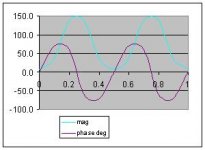
I'm not sure I understand what you are saying. Do you agree with the equation I gave? When I use this equation to calculate the impedance of the transmission line versus distance between source and load I find both the magnitude and phase of the impedance vary.
For example, if Zo (the characteristic impedance, which is real) is 50 ohms and Zload is 8 ohms, then Z(mag) varies between about 8 and 138 ohms and Z(phase) varies between -71 deg and +71 deg. You may be able to see this in the attachment if it works.
Zo is independent of cable length as you say. But that is the way it is defined. But the impedance of the cable as seen by the source will vary in real and imaginary terms along its length.
What am I missing?
BAM
Attachments
Is Nelson on drugs?
"Yes. But not in any realworld situation."
I agree that within the audio band the reactive impedance the amp sees due to speaker cable loading mismatch is not relevant. Besides, the Zload value is all over the place in this band anyhow due to the speaker load being on the booze.
Although Nelson may well have fried his brain in the pursuit of audio nirvanah, I think he's talking about affects in the 10s of MHz affecting the amp.
Let me explore this (cause I haven't worked this out yet). Suppose the speaker cable is 5m long. C is 300000km/s (I think) and suppose as you suggest the velocity is C/2. This makes the cable length equal to one wavelength at 30MHz (I think). Now the open-loop bandwidths of some amps does get into the 10MHz+ area in some designs - so I can imagine such amps getting disturbed by the impedance phase shifts of the cable if precautions are not taken. I should think this is a rare occurance, though. Perhaps Nelson will comment on this.
Ok,
What would be an adequate fixture for testing an amplifiers response to the speaker cable & speaker affect on an amp?
----------------
I was thinking something like:
Get 2 matched amps.
Connect a white/pink noise generator to both.
Load 1 amp with your standard speaker/cable.
Load the other amp with an 8 Ohm resistor.
Connect both amp outputs to differential probes.
Connect both probes to a FFT analyzer, calibrate the gain difference between both probes for minimal distortion.
-----------------
Plot results…
Does anyone out ther have such resources?
traderbam said:Steve,
I'm not sure I understand what you are saying. Do you agree with the equation I gave? When I use this equation to calculate the impedance of the transmission line versus distance between source and load I find both the magnitude and phase of the impedance vary.
The equation's fine.
As for the graph, can you tell me exactly what the "phase" is that's being plotted? It apparently is not the voltage/current phase (caused by the reactive elements in the line) I have been referring to. It appears to be the phase of the direct and reflected waves, seeing as the phase passes through zero every quarter wavelength.
se
The phase in the graph is the relationship between current and voltage at the source end of the cable. As if the cable were an LCR network.
Z(mag) = SQRT[ Zload^2 + (Zo.tanW)^2 ] / SQRT[ Zo^2 + (Zload.tanW)^2 ]
Z(phase) = arctan[ Zo.tanW/Zload ] - arctan[ Zload.tanW/Zo ]
The L/m and C/m of the cable in combination with the Zload are what cause the reflections and the impedance changes. I don't think the two can be meaningfully separated. I find this stuff a bit of a mind bender - I just hope like hell that Maxwells equations don't appear in this thread or I'm toast.
traderbam said:The phase in the graph is the relationship between current and voltage at the source end of the cable. As if the cable were an LCR network.
But at the frequencies we're talking about here, it's not an LCR network.
Let's go back to the original equation for the input impedance of the line:
<center>
<img src="http://www.q-audio.com/images/eq1.jpg">
</center>
Both <i>Z</i><small><sub>O</sub></small> and <i>Z</i><small><sub>L</sub></small> are purely resistive. So how do you come up with a phase angle other than 0?
Perhaps I'm missing something obvious here. I just don't see it.
se
I just hope like hell that Maxwells equations don't appear in this thread or I'm toast.
Hehehe. How 'bout Maxwell's silver hammer?
 Er, or red as the case may be.
 se
Brian Guralnick said:Ok,
What would be an adequate fixture for testing an amplifiers response to the speaker cable & speaker affect on an amp?
----------------
I was thinking something like:
Get 2 matched amps.
Connect a white/pink noise generator to both.
Load 1 amp with your standard speaker/cable.
Load the other amp with an 8 Ohm resistor.
Connect both amp outputs to differential probes.
Connect both probes to a FFT analyzer, calibrate the gain difference between both probes for minimal distortion.
-----------------
Plot results…
Does anyone out ther have such resources?
Ah b'lieve Nelson do.
se
Cable stuff
How about taking a single amp, connecting a test cable, drive with a square wave of say 10kHz (which has appreciable harmonics up to 100kHz), check response with/without termination, different cable lengths etc. Can be done by (almost) anyone. What are we looking for anyway?
Jan Didden
How about taking a single amp, connecting a test cable, drive with a square wave of say 10kHz (which has appreciable harmonics up to 100kHz), check response with/without termination, different cable lengths etc. Can be done by (almost) anyone. What are we looking for anyway?
Jan Didden
Steve Eddy wrote:
You posted the answer yourself within your own mail:
It is the term
(ZL + j Z0 *tan (beta*l)) / (Z0 + j ZL * tan (beta*l))
that makes the input impedance look heavily frequency dependant.
The only exception is the situation where ZL=Z0.
Q.E.D.
Regards
Charles ( HB9GBQ )
Both ZO and ZL are purely resistive. So how do you come up with a phase angle other than 0?
You posted the answer yourself within your own mail:
It is the term
(ZL + j Z0 *tan (beta*l)) / (Z0 + j ZL * tan (beta*l))
that makes the input impedance look heavily frequency dependant.
The only exception is the situation where ZL=Z0.
Q.E.D.
Regards
Charles ( HB9GBQ )
Hmm... negative impedance of Aleph current source in parallel with positive impedance of the output gain transistor = zero open loop output impedance? How did I ever overlook this?
Boy, the more I stare at the Aleph and especially the Aleph-X schematic, the more I like these circuits! I've gotta hand it to you, Nelson. Years ago, I used to dismiss the Pass Labs stuff as brute-force, inefficient, purist baloney (while I built Mullard/Williamson tube circuits and read D. Self's work like a bible...
  can you imagine that!?! heh, makes me chuckle now). Now I've fallen head over heels for the Aleph-X.
  It's truly a thing of beauty and elegance.
Cheers Nelson.
and now back to our regularly scheduled programme...
Boy, the more I stare at the Aleph and especially the Aleph-X schematic, the more I like these circuits! I've gotta hand it to you, Nelson. Years ago, I used to dismiss the Pass Labs stuff as brute-force, inefficient, purist baloney
(while I built Mullard/Williamson tube circuits and read D. Self's work like a bible... can you imagine that!?! heh, makes me chuckle now). Now I've fallen head over heels for the Aleph-X. It's truly a thing of beauty and elegance.Cheers Nelson.
and now back to our regularly scheduled programme...
Steve wrote: "Both ZO and ZL are purely resistive. So how do you come up with a phase angle other than 0?"
Oh, this is just the mathematics at work. The j operator (aka sqrt of -1) does this. In general if X=A + jB the phase angle of X is arctan(B/A) and the magnitude is SQRT(A^2+B^2). It is a pythagorean model...A being the adjacent side of the triangle and B he opposite side. The magnitude is the hypotenuse and the phase angle is the angle between adjacent and hypotenuse.
In this formula Zo is a real constant but Zload can be reactive and the formula still applies.
traderbam wrote:
It is even more extreme: Even when both, Zo and Zload, are real Zin will still show a frequency dependant (and therefore complex) behaviour.
The only exception is the situation Zo = Zload
Regards
Charles
In this formula Zo is a real constant but Zload can be reactive and the formula still applies.
It is even more extreme: Even when both, Zo and Zload, are real Zin will still show a frequency dependant (and therefore complex) behaviour.
The only exception is the situation Zo = Zload
Regards
Charles
traderbam said:"negative impedance of Aleph current source in parallel with positive impedance of the output gain transistor = zero open loop output impedance"
The Aleph current source does not do this as a practical matter.
The Aleph current source ghosts the load impedance, usually
at a value of -2X. This applies equally to resistive and reactive
loads, and makes the output gain transistor behave as if
the impedance of the load is double its true value.
Heh. Quite right. No wonder I'd "overlooked" that... duh. 
Well, at least the current source has the effect of reducing the open loop output impedance, or another way of thinking about it is doubling the load impedance seen by the gain transistor. Hm.
OK, nothing to see here... move along.
Well, at least the current source has the effect of reducing the open loop output impedance, or another way of thinking about it is doubling the load impedance seen by the gain transistor. Hm.
OK, nothing to see here... move along.
- Status
- This old topic is closed. If you want to reopen this topic, contact a moderator using the "Report Post" button.
- Home
- Amplifiers
- Solid State
- High impedance out amps VS as low as possible.