forgot to add, my IC looks like the one on the left too.
allso i attach a picture of an assembled kit i mentioned.
I just got the email with the picture, i wanted to see if the IC is the same as what i use.
i hope it helps
allso i attach a picture of an assembled kit i mentioned.
I just got the email with the picture, i wanted to see if the IC is the same as what i use.
An externally hosted image should be here but it was not working when we last tested it.
i hope it helps
It sounds to me like this thing is oscillating. I assume the rails are well decoupled.
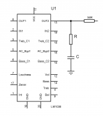
Looking at the schematic in the data sheet, I see what looks like an emitter follower output stage. Could be this is your problem - they are notorious for local parasitic osclillation at many MHz if you are not careful, and connecting a small cap from the output to ground would in fact help cure the problem. What MIGHT be happening here is the lead inductance between the output and the load means the load impedance seen by the output stage increases with frequency and this creates the opportunity to oscillate (you have something akin to a Colpitt's oscillator structure). I would try a 10-22 Ohm resistor in series with the output, located as close to the 1036 as possible, and then directly from the 1036 output to ground, a small Zobel network - say 0.2 to 1nF in series with a 22 Ohm resistor. You will need to experiment a bit with the C value - start with a low value and then work you way up.
I am sure you can clean this thing up. BTW, the volume control misbehaving the way to describe is a classic indication that you have HF oscillation.
Good luck!
Last edited:
i have managed to give a go for it.
results are the verry same, adding a small capacitor and powering it from battery, adding the small zobel network and the resistor had no impact on tone controll misbehavior.
still no clue, but the kit is on its way, will see if the kit works or not..
results are the verry same, adding a small capacitor and powering it from battery, adding the small zobel network and the resistor had no impact on tone controll misbehavior.
still no clue, but the kit is on its way, will see if the kit works or not..
10 ohm 5 watt resistor was used , and capacitor was 330 pf ceramic.
same kind of resistor was used as series resistor too. (they are ordered as part of a xover, only low ohm value ones i have..)
Allso since i had parts at hand i did try 15 pf, and 220 pf.
no change
there is some celebration or what in this darn country, kit still has not arrived yet.
same kind of resistor was used as series resistor too. (they are ordered as part of a xover, only low ohm value ones i have..)
Allso since i had parts at hand i did try 15 pf, and 220 pf.
no change
there is some celebration or what in this darn country, kit still has not arrived yet.
You may have to try something up in the 1nF range. Make sure your resistor is not inductive either. If you are oscillating at 40+ MHz, you don't need much resistor inductance to make your Zobel less than ideal. did you insert the series resistor with the output? This is very important.
rgds
rgds
forgot to add, my IC looks like the one on the left too.
allso i attach a picture of an assembled kit i mentioned.
I just got the email with the picture, i wanted to see if the IC is the same as what i use.
An externally hosted image should be here but it was not working when we last tested it.
i hope it helps
where can you get these circuit boards from ? I need 6 of them.
Bonzai,
I like more your Zobel network instead of my fist solution tying the output to GND directly with 220pF.
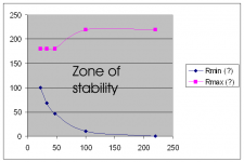
I experimented with a 56R resistor in serie with the output and with different values for R and C from output to ground. For some capacitor values, I determined the minimum and maximun value of the resistor for stability. Here are the results.
Maybe the shape of the curve "Rmax" could be smoother, but I had no resistors with intermediate values handy.
The measurement were taken with scope and a FET probe (3pF at input) behind the 56R
Sorry, the values are in the .txt, cause I didn't find how to format in columns...
I like more your Zobel network instead of my fist solution tying the output to GND directly with 220pF.
I experimented with a 56R resistor in serie with the output and with different values for R and C from output to ground. For some capacitor values, I determined the minimum and maximun value of the resistor for stability. Here are the results.
Maybe the shape of the curve "Rmax" could be smoother, but I had no resistors with intermediate values handy.
The measurement were taken with scope and a FET probe (3pF at input) behind the 56R
Sorry, the values are in the .txt, cause I didn't find how to format in columns...
Attachments
darn celebration is still on...
Thank You Daniel and Bonsai for ahring a possible fix
I will try to find parts to make a zobel according to Daniel's tests.
RainWulf, I will ask the shop as soon as possible if they can get more of these kits.
That is, if i found the kit working properly.
Thank You Daniel and Bonsai for ahring a possible fix
I will try to find parts to make a zobel according to Daniel's tests.
RainWulf, I will ask the shop as soon as possible if they can get more of these kits.
That is, if i found the kit working properly.
darn celebration is still on...
Thank You Daniel and Bonsai for ahring a possible fix
I will try to find parts to make a zobel according to Daniel's tests.
RainWulf, I will ask the shop as soon as possible if they can get more of these kits.
That is, if i found the kit working properly.
thank you for this.
This seems to be the best way to control the signal on multiple channels at once for my computer sound system.
Can you link up multiple boards to one dc level? For example, can one pot control the volume on multiple boards?
yes, the controlls are DC .
Not sure if the built in precision voltage source will be able to deal with many boards, it is not impossible at all. I did not check the current rating and current requirements.
Even so, an external voltage source can be used as far as I know.
If you are only after controlling the volume, you may as well try to build a handfull of
http://www.nxp.com/documents/data_sheet/TDA7052B.pdf
these guys.
The kit I ordered comes without pots, and cost+shipping is around 10ero for eatch one.
the TDA7052 is around 1 euro including the external components required for it to work.
Great - looks like you guys have got it nailed!
Those emitter followers (especially if they are high gain NPN's) can esily oscillate at 10's of MHz, so the Zobel is a neat trick, but don't forget to add the series resistor as shown by daniel23
Happy listening.
(I am surprised that Natsemi have not mentioned this in the data sheet or in a realted app note. If there's a NatSemi apps engineer around, how about it?)
YEEEY!!
MY KIT FINALY ARRIVED!
okay, so whats the bad news?
It does work as I suspected it would.
Ic was pre-soldered, rest took only a few minutes.
the IC is like the one on the RIGHT side of pic in post number 16
http://www.diyaudio.com/forums/chip...cy-sine-wave-lm1036-output-2.html#post2496067
but i got a bit of problem.
Since i made it, i fired it up.
Nowthen.
My clumsy tda1557Q power amp wen finished acted more like a radio.
No problem, 15 pf cap on the inputs to the ground did finish that bad behaviour.
now comes the problem, if i DO add this tone controll to the amp, it sounds like a radio AGAIN.
I did add 15 pf ceramic to its inputs. with NO use.
So.. what now?
Use a set of larer caps? like something .. 220 pf or 330 pf ones?
The amp has no case, the Lm chip panel is not in a case.
The lm is powered from 3x4.5 battery packs giving 13,5 volts.
The "powa amp" utilises some unknown psu giving dc 15 volts at output.
I did not use shielded cables, just some ordinary wires with jacks on them to connect this thing between my "powa amp" and the computer.
If anyone is intrested in component values and PCB, i can upload them.
The design it self is quite quiet.
My other problem is, even if i reduce the "volume" pot to zero, i can still hear the music. Its not loud, it is hard to notice, still it does not gives what i expected.
so.. any help on what to do with its inputs to get rid of RF noise?
(I can tell it is RF, it picks up the local radio station, i can hear and understand it absolutely fine, just like if i had a radio.)
This problem may be hard to overcome. What frequency is the radio ?
If the frequency is around 100MHz, then the impedance of 15 pF capacitors is a little more than 100R. Well, note at this frequency, each centimeter of wire has also an inductance of about 10 nH. This means the wires must be as short as possible.
The first I would try would be to put the whole circuit (power Amp and LM1036) on a ground plane, about 10 to 15mm above. A tinned steel sheet may be suitable. All inputs AND outputs tied to this ground plane with 2.2nF caps. Not to forget the power supply.
If it cures, then you can try to remove some of the caps until you find the culprit...
May be you should also use shielded cables. The shield tied as short as possible to the ground plane.
Previous post is gone out too fast. I reworked it as follow.
This problem may be hard to overcome. What frequency is the radio ?
If the frequency is around 100MHz, then the impedance of 15pF capacitors is a little more than 100R. That will be too much in most of the cases. For testing, ceramic capacitors with a value of 1nF or 2.2nF would be more suitable.
Well, at this frequency, each centimeter of wire has also an inductance of about 10nH. This means the wires must be as short as possible.
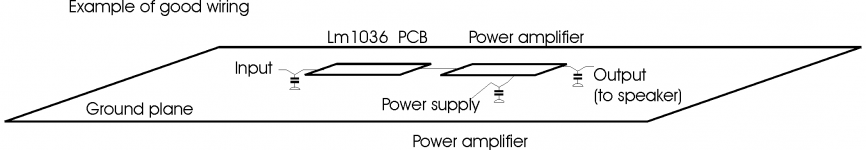
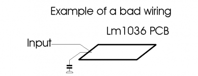
At the first, I would try would be to put the whole circuit (power Amp and LM1036) on a ground plane, about 10 to 15mm above. A PCB unetched large enough or a tinned steel sheet may be suitable as long you can solder on it. EACH wire from all inputs AND outputs tied to this ground plane with 2.2nF caps. Not to forget the power supply. On example of wiring in the attached drawing you can see how to connect the caps to obtain the best filtering effect. Such a wiring limit the common impedance. The second picture show the "not so good" wiring of the caps.
If it cures, then you can try to remove some of the caps until you find the culprit...
May be you should also use shielded cables. The shield tied as short as possible to the ground plane.
This problem may be hard to overcome. What frequency is the radio ?
If the frequency is around 100MHz, then the impedance of 15pF capacitors is a little more than 100R. That will be too much in most of the cases. For testing, ceramic capacitors with a value of 1nF or 2.2nF would be more suitable.
Well, at this frequency, each centimeter of wire has also an inductance of about 10nH. This means the wires must be as short as possible.
At the first, I would try would be to put the whole circuit (power Amp and LM1036) on a ground plane, about 10 to 15mm above. A PCB unetched large enough or a tinned steel sheet may be suitable as long you can solder on it. EACH wire from all inputs AND outputs tied to this ground plane with 2.2nF caps. Not to forget the power supply. On example of wiring in the attached drawing you can see how to connect the caps to obtain the best filtering effect. Such a wiring limit the common impedance. The second picture show the "not so good" wiring of the caps.
If it cures, then you can try to remove some of the caps until you find the culprit...
May be you should also use shielded cables. The shield tied as short as possible to the ground plane.
Attachments
thats kinda wierd, i nevber had such think happening.
By default i tie inputs to ground via 15 pf capacitor, and it allways workt flawlessly.
Anyways i moved the pcb around 2 centimeters, and radio is gone.
I have to verry precisely move it around and there is only 1 spot when it picks up the radio. Even if i rotate the pcb its gone.
strange.
well anyways it got sorted out so to say.
Now comes a nother question, even if i turn the volume pot all the way down I can still hear the music from the speakers. It is verry verry weak, but its still comming.
Any ways to make it reduce signal lvl further so volume set to zero does what it should?
Other than that i em more than statisfied with the circuit it self.
And thank You for the help
volume?
Hey Arty,
Did you manage to solve that volume control problem?
I have the same issue here. also the volume is not fully dimmed when the volume pot is full down. i measure 100mV on the volume input at pin 12, what means that it should be on minimal..
regards,
Erwin.
Hey Arty,
Did you manage to solve that volume control problem?
I have the same issue here. also the volume is not fully dimmed when the volume pot is full down. i measure 100mV on the volume input at pin 12, what means that it should be on minimal..
regards,
Erwin.
The fix in post 22 (http://www.diyaudio.com/forums/chip...cy-sine-wave-lm1036-output-3.html#post2499672) worked for me as well. I used 33 ohms in series with 680pF to ground, and a 220 ohm resistor to the output.
Also noticed this on the TI forum. They suggested the series resistor to the output but not the Zobel:
https://e2e.ti.com/support/amplifiers/audio_amplifiers/f/6/t/386223
Also noticed this on the TI forum. They suggested the series resistor to the output but not the Zobel:
https://e2e.ti.com/support/amplifiers/audio_amplifiers/f/6/t/386223
- Status
- This old topic is closed. If you want to reopen this topic, contact a moderator using the "Report Post" button.
- Home
- Amplifiers
- Chip Amps
- High frequency sine wave on the LM1036 output