Thinking about getting a higher current supply for testing amplifiers under load. Car amplifiers that is, ") .
.
I have a prism sound dscope and am able to do power sweeps etc, been doing it for quite awhile.
I'm constructing 4 banks of a bit over 1000W capable 4ohm loads that are fan cooled. I'll be able to parallel the banks up later. They are 45ea of the vishay 2.2 ohm 25 watt resistors. 9 series/5 parallel fwiw. Should be pretty nice.
I currently have a tekpower 15v 60A (and 5A 30v tekpower for debug). Kind of limited for the higher power amps I'm repairing, especially if I want to test below four ohms.
Spark Usina makes an interesting offering out of Brazil. Will do 220A at 15v. Decent price.
I know everyone will suggest this and I've built server power supplies and have one. I haven't figured out how to bypass the overvoltage. So it's only good to 13.8v which isn't ideal. Pretty common to hit the overvoltage barrier with sever supplies I believe.. I used this one before I got the high power tekpower.
I have access to 220v 20A at my workbench fwiw.
Wondering if I'm missing another option? Would like to be able to do 200A at 15v at least. Needs to monitor and display both current and voltage too.
--------
Ended up buying x3 of HP dps-1200fb hstns-pd19 and modifying... This thread became kind of a how-to..
.I have a prism sound dscope and am able to do power sweeps etc, been doing it for quite awhile.
I'm constructing 4 banks of a bit over 1000W capable 4ohm loads that are fan cooled. I'll be able to parallel the banks up later. They are 45ea of the vishay 2.2 ohm 25 watt resistors. 9 series/5 parallel fwiw. Should be pretty nice.
I currently have a tekpower 15v 60A (and 5A 30v tekpower for debug). Kind of limited for the higher power amps I'm repairing, especially if I want to test below four ohms.
Spark Usina makes an interesting offering out of Brazil. Will do 220A at 15v. Decent price.
I know everyone will suggest this and I've built server power supplies and have one. I haven't figured out how to bypass the overvoltage. So it's only good to 13.8v which isn't ideal. Pretty common to hit the overvoltage barrier with sever supplies I believe.. I used this one before I got the high power tekpower.
I have access to 220v 20A at my workbench fwiw.
Wondering if I'm missing another option? Would like to be able to do 200A at 15v at least. Needs to monitor and display both current and voltage too.
--------
Ended up buying x3 of HP dps-1200fb hstns-pd19 and modifying... This thread became kind of a how-to..
Last edited:
I don't know if they're still available but they make (made?) 5v server supplies. The ones I have are rated for 120 amps. I used them in parallel (3 in series and then those in parallel).
Unless the server supplies were limited to 13.8v by the transformer, it should be easy enough to find a way to get them over 13.8. If it's a supply that works on any voltage between 110 and 220, the transformer shouldn't be an issue when run on 220v.
It would also be possible to build a voltage regulator to take the voltage from batteries or a high-current transformer (welding machine, possibly) down to 15v.
Hi
there are modules made for that!!
https://en.yuyiparts.com/nemic-lambda-ews3000t-12-power-supply-12v-250a.html
there are modules made for that!!
https://en.yuyiparts.com/nemic-lambda-ews3000t-12-power-supply-12v-250a.html
here on aliexpress
https://fr.aliexpress.com/item/1005003975578693.html?gatewayAdapt=glo2fra
For monitoring at these power levels you must have an ammeter clamp because the shunt at these current values are monstrous!
https://fr.aliexpress.com/item/1005003975578693.html?gatewayAdapt=glo2fra
For monitoring at these power levels you must have an ammeter clamp because the shunt at these current values are monstrous!
Last edited:
Oh, budget is a factor.
If it wasn't I would have grabbed the spark usina supply already for under $300.
https://www.corporationlm.com/Spark-Usina-220A-Digital-Automotive-Supply-14.4V-220V-Car-Audio
If it wasn't I would have grabbed the spark usina supply already for under $300.
https://www.corporationlm.com/Spark-Usina-220A-Digital-Automotive-Supply-14.4V-220V-Car-Audio
I actually finally got a lead on a way to maybe get past the over voltage protection last night on that supply.. not sure about current sharing though. Is it just as simple as getting them all dialed in even and winging it? Or is there a current share and that I should be utilizing?
A short length of 6 or 8g wire or current shunts in series with each of the parallel supplies will help in current sharing but it's not critical. If you want to get them close, put shunts in series with each supply and adjust the voltage on the supplies to match current at the highest output level.
I posted this on a HSTNS-PD19 thread on rc groups too but I'm gonna cross-post this here.
Where I'm at currently with this project.
----
I have a few of these HSTNS-PD19 I'm working on for car audio amp testing, want to run 3 in parallel at 14.4v volts (off of 220v).
I have found how to disable the OVP!!! Well, to an extent. It is making it to 14.08v now before either a secondary protection kicks in, some other sensor becomes out of range, or the unit is just plane wigging out with output voltage quite low and bouncing some (which more or less is what happens when hitting OVP anyway.)
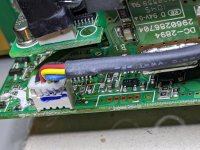
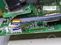
Initially, the resistor near the pot was a 18.7k. I increased that to 20k at first. Maxed out at 12.7v after moving the pot up just a bit.. (the known ovp protection kick-in point).
Moving on to ovp (which i finally found.. pretty sad how long that took lol). Is just a simple R divider to the micro on the back side of the daughter board. Stock is 20k/3.74k.
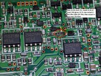
I first added 20k to the 3.74k to get 3.151k (my rough calc said this should kick in ovp around 15.3v).
Then back to the pot side.. Changed that resistor to 22k, could now swing 13.6v (ccw) to 14.05v (cw).. cool i thought.
Went to 24k which was a bit of a leap, no dice.. Protection or wig-out state even at ccw pot.
F'd around and finally found a parallel combination of resistors that allowed me to boot ccw with the pot (68k||33k=22.218k).
Still hitting the ovp at around 14.08v (i thought). I changed the ovp circuit resistor to 3k. I now start at 13.72V and max out at 14.08v with pot ccw and cw.
There is a comparator circuit on the bottom of the main pcb that takes output voltage into the comparator input, I did play around there too after all of the above, no luck there. FYI
Not sure what I'll poke next.
Of course I'm wary of exceeding (or approaching) the 16v limit of the output caps, and I have NOT done any load testing at higher output as of yet.
Tbc.. thoughts welcome. Don't see a whole lot about this version of this supply, figured this was a good place to put this
 .
.
Where I'm at currently with this project.
----
I have a few of these HSTNS-PD19 I'm working on for car audio amp testing, want to run 3 in parallel at 14.4v volts (off of 220v).
I have found how to disable the OVP!!! Well, to an extent. It is making it to 14.08v now before either a secondary protection kicks in, some other sensor becomes out of range, or the unit is just plane wigging out with output voltage quite low and bouncing some (which more or less is what happens when hitting OVP anyway.)
Initially, the resistor near the pot was a 18.7k. I increased that to 20k at first. Maxed out at 12.7v after moving the pot up just a bit.. (the known ovp protection kick-in point).
Moving on to ovp (which i finally found.. pretty sad how long that took lol). Is just a simple R divider to the micro on the back side of the daughter board. Stock is 20k/3.74k.
I first added 20k to the 3.74k to get 3.151k (my rough calc said this should kick in ovp around 15.3v).
Then back to the pot side.. Changed that resistor to 22k, could now swing 13.6v (ccw) to 14.05v (cw).. cool i thought.
Went to 24k which was a bit of a leap, no dice.. Protection or wig-out state even at ccw pot.
F'd around and finally found a parallel combination of resistors that allowed me to boot ccw with the pot (68k||33k=22.218k).
Still hitting the ovp at around 14.08v (i thought). I changed the ovp circuit resistor to 3k. I now start at 13.72V and max out at 14.08v with pot ccw and cw.
There is a comparator circuit on the bottom of the main pcb that takes output voltage into the comparator input, I did play around there too after all of the above, no luck there. FYI
Not sure what I'll poke next.
Of course I'm wary of exceeding (or approaching) the 16v limit of the output caps, and I have NOT done any load testing at higher output as of yet.
Tbc.. thoughts welcome. Don't see a whole lot about this version of this supply, figured this was a good place to put this
Attachments
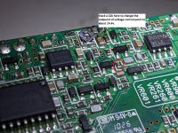
and this..
--
Well, some good news. I did try a 1ohm load at 13.9V and it was stable. Sooo that's good.
 .
.
I'm kind of guessing that the supplies are designed to drive up to this 14.08v number when current sharing/sensing and there are losses in the system, that number could be where some secondary limit kicks in in the design.
--
Well, some good news. I did try a 1ohm load at 13.9V and it was stable. Sooo that's good.
I'm kind of guessing that the supplies are designed to drive up to this 14.08v number when current sharing/sensing and there are losses in the system, that number could be where some secondary limit kicks in in the design.
Ok, finally got there. Smh....
DO THE BELOW AT YOUR OWN RISK AND REALIZE I HAVE NOT TESTED FOR RELIABILITY.
I load tested at .375Ohm and voltage drop was from 14.40 to 14.25v, not too shabby.
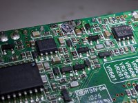
One thing that is worrisome though is that the ucc37323 driver is running really hot, like 118C after a minute or so. Need to circle back to that. It's on the inside side of the long side board, near the top (soic8 package between a couple wired headers).
Scoped around a bit and waveforms look mostly ok, probably more digging to do.
And another sort of scary fyi, the last hack I did to get from 14.08v to 15v was just trial and error lol. I picked out non-standard values on the side board and tried raising and lowering resistance until something worked.. I was having zero luck with other methods. Sooo yeah I'm not entirely sure where in the circuit this tweak is
 .
.
Pics attached enjoy
DO THE BELOW AT YOUR OWN RISK AND REALIZE I HAVE NOT TESTED FOR RELIABILITY.
I load tested at .375Ohm and voltage drop was from 14.40 to 14.25v, not too shabby.
One thing that is worrisome though is that the ucc37323 driver is running really hot, like 118C after a minute or so. Need to circle back to that. It's on the inside side of the long side board, near the top (soic8 package between a couple wired headers).
Scoped around a bit and waveforms look mostly ok, probably more digging to do.
And another sort of scary fyi, the last hack I did to get from 14.08v to 15v was just trial and error lol. I picked out non-standard values on the side board and tried raising and lowering resistance until something worked.. I was having zero luck with other methods. Sooo yeah I'm not entirely sure where in the circuit this tweak is
Pics attached enjoy
Attachments

Is the supply voltage for the driver IC too high?
If not, lowering it may help it run cooler.
The IC has a thermal pad on the bottom side. You may be able to use that or add a heatsink to the top (binder clip, gap pad, maybe a piece of copper).
If you move the feedback to the load (beyond the wiring or shunt resistors) will help maintain better regulation at the load.
Hi, have you changed anything else besides these three resistors? My power supply won't start up in this configuration.Ok, finally got there. Smh....
DO THE BELOW AT YOUR OWN RISK AND REALIZE I HAVE NOT TESTED FOR RELIABILITY.
I load tested at .375Ohm and voltage drop was from 14.40 to 14.25v, not too shabby.
One thing that is worrisome though is that the ucc37323 driver is running really hot, like 118C after a minute or so. Need to circle back to that. It's on the inside side of the long side board, near the top (soic8 package between a couple wired headers).
Scoped around a bit and waveforms look mostly ok, probably more digging to do.
And another sort of scary fyi, the last hack I did to get from 14.08v to 15v was just trial and error lol. I picked out non-standard values on the side board and tried raising and lowering resistance until something worked.. I was having zero luck with other methods. Sooo yeah I'm not entirely sure where in the circuit this tweak is.
Pics attached enjoy
Coming together slowly.. I'll post updates.
Figured I would post this here, flat out bargain for c13 connections w/ 14awg .. I'm going to hack them to connect to 220 volt obviously with 12 awg main cable.
https://smile.amazon.com/gp/aw/d/B08W9GMQ6Y?psc=1&ref=ppx_pop_mob_b_asin_image
Figured I would post this here, flat out bargain for c13 connections w/ 14awg .. I'm going to hack them to connect to 220 volt obviously with 12 awg main cable.
https://smile.amazon.com/gp/aw/d/B08W9GMQ6Y?psc=1&ref=ppx_pop_mob_b_asin_image
- Home
- General Interest
- Car Audio
- High current supply for testing