Never mind the small resistance. It was my power supply. Without power supply wires I read OL with continuity test everywhere I read 4 ohms before.
What do you think about voltages on IC701:
Voltages on IC701 after zeners are reinstalled and all the other opamps are still out:
01: -9,23
02: 0,7
03: 0,04
04: 0,04
05: -0,43
06: -10,83
07: -0,41
08: -1,62
09: -3,68
10: -0,01
11: 9,5
12: 0
13: -0,91
14: -0,94
15: -0,95
16: -9,73
Datasheet: NJM13600D datasheet pdf datenblatt - New Japan Radio - DUAL OPERATIONAL TRANSCONDUCTANCE AMPLIFIER?? ::: ALLDATASHEET :::
Removed the last opamp from board, voltages did not go higher.
I think that the transformers have gone bad. I get 7k ohm of resistance between B+ and RCA shield. 0.2V between GND and RCA shield.
When amp is working there is 0,5V to 2V on secondary windings of the transformer. It was not there before but I think Ive made things worse because I have removed the transformers 3 times already.
Every time I do something to transformers I get different rail voltages afterwards.
It's unlikely that the transformers are defective. A shorted transformer would cause excessive current draw or 12v leaking to the secondary.
The voltages on the 13600 are not reliable with the op-amps out of the circuit.
Why did you remove all of the op-amps when there was DC on only one or two of them?
Do you have plans to buy a scope any time soon?
The voltages on the 13600 are not reliable with the op-amps out of the circuit.
Why did you remove all of the op-amps when there was DC on only one or two of them?
Do you have plans to buy a scope any time soon?
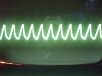
Finally had time to come back to this amp as well.
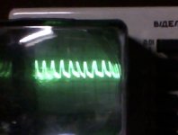
With my very old scope I was able to see the waveform on FETs gates, it should be square, right?
Anyway what I got is on the attached photo, v/del is I think 5V and time 0,2us/del but Im not sure, the explanations for buttons are in russian, I speak some russian but technical terms I do not know so well.
Sorry about poor picture quality and never mind the fish eye effect, the screen on the thing is so small that it actually has a magnifying glass in front of it. That glass creates the fish eye effect, next time I know to take the picture "straight".
Attachments
Do you get a square wave at the output pins of the power supply driver IC?
If you set it to display only 3-4 cycles, you'll get a bit better resolution.
If this is at 0.2us, the frequency is too high. Do you have a sine wave generator or a test tone CD? if so, set either to 20khz and adjust the timebase to display 2 cycles. The power supply shouldn't have more than 4 cycles at that setting. Make a mark so that you can remember the setting.
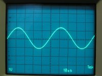
For reference, the attached images show a 20k sine wave and a 38k square wave from a power supply (gate drive). These are at 10us.
If you set it to display only 3-4 cycles, you'll get a bit better resolution.
If this is at 0.2us, the frequency is too high. Do you have a sine wave generator or a test tone CD? if so, set either to 20khz and adjust the timebase to display 2 cycles. The power supply shouldn't have more than 4 cycles at that setting. Make a mark so that you can remember the setting.
For reference, the attached images show a 20k sine wave and a 38k square wave from a power supply (gate drive). These are at 10us.
Attachments
I cant get to driver IC with my probe, because it is located on a card between transformers.
I managed to check the pins of that card, did not find squarewave from them. Found similar waveform, that was on gates.
I have your tutorial and the test CD.
Seems that something on the driver card has failed?
I managed to check the pins of that card, did not find squarewave from them. Found similar waveform, that was on gates.
I have your tutorial and the test CD.
Seems that something on the driver card has failed?
Cant still figure out this scope.
Anyway, I measured voltages on KA7500.
01: -0,03 (why minus?)
02: 4,9
03: 0,06
04:0,18
05:1,67
06:3,43
07:0
08:9,59
09:1,75 (low?)
10:1,85 (low?)
11:9,57
12:8,85
13:4,9
14:4,9
15:4,9
16:0,88
Besides the -0,03 and 1.75/1.85 on output, other pins look good.
Anyway, I measured voltages on KA7500.
01: -0,03 (why minus?)
02: 4,9
03: 0,06
04:0,18
05:1,67
06:3,43
07:0
08:9,59
09:1,75 (low?)
10:1,85 (low?)
11:9,57
12:8,85
13:4,9
14:4,9
15:4,9
16:0,88
Besides the -0,03 and 1.75/1.85 on output, other pins look good.
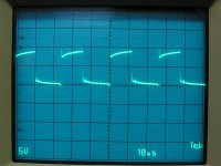
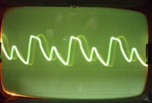
Got a bit better oscilloscope, they are hard to find used here in Estonia. Yesterday I saw that there is one for sale, so I picked it right up.
Took some new photos of waveforms produced by PS chip.
First one is from PS chips ouput, other photos are on the gate of FET amp idling, amp producing audio.
Took some new photos of waveforms produced by PS chip.
First one is from PS chips ouput, other photos are on the gate of FET amp idling, amp producing audio.
Attachments
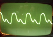
Pin 6 was 3,43 with limiter inline. Resistor reads 302, I measured 3k ohm of resistance across the resistor.
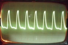
Waveform on pin 5 is a bit different from the photo of pin 5 waveform in your tutorial. Tried to probe another amp which I have lying around. From that amp I got the exact replica of waveform from your tutorial.
Photo attached, again 1us/del, 1v/del.
What is the value of the cap connected to pin 5? I did not see any writings on it.
I guess the marking is on the other side, I have to desolder the cap to read it.
Attachments

Last edited:
- Status
- This old topic is closed. If you want to reopen this topic, contact a moderator using the "Report Post" button.
- Home
- General Interest
- Car Audio
- Hifonics Nemesis NX-400 low rail voltage