Hi,
I'm in the process of putting together a high powered version of the Aleph X. I'm using CRC power supply filtering to get 22 volt rails with an 18 volt transformer.
My question is this: With recommended power requirements around 800va, would I be able to use two 400 VA transformers instead? Any advantages or disadvantages to this method? I can get 400VA transformers cheaply at Antek.
Thanks
Okay, maybe I should have mentioned this in my first post: I actually have no idea the CRC design for this amp should look like. I've searched high and low and can't find an example. I tried the simulation software, but had no idea how to use it.
I'm trying to build the design from here:
http://www.facstaff.bucknell.edu/esantane/movies/wuffwaff.html'
So it looks like I need 22v rails, but what sort of transformer and what sort of CRC circuit would I need?
Also, to clarify my previous post, the reason I'm looking into 2x400va transformers is because I can't find anything that big in one transformer. I've seen various references to victoria magnetics, but I can' t seem to find a link for a company or a supplier. Any help?
CRCRC Design
Hi everyone,
I am also working on the high powered Aleph-X design based on the hifi zen rev 1.0 boards that systemerror909 is using. Attached is a figure for a CRCRC design that I have tried to figure out myself. I have based it off of other posts and the basic knowledge I have in circuit design. I am especially concerned about having the correct power and voltage ratings for the resistors and capacitors respectively.
I also tried the demo software and it made me very confused. I am hoping that some good samaritan may take some time to look this over and tell us if it will even work or what needs correction.
We are building the 100W Aleph-X with 3 power transistors in each bank for a total of 12 transistors per channel.
Thanks for any input you may have.
Jeff...
Attachments
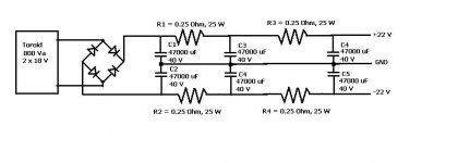
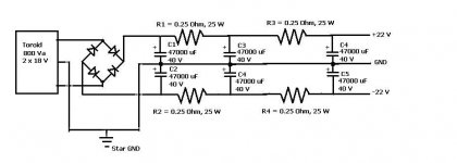
Gnd
The GND should be connected to the center tap of the transformer.
2x18V gives 3 wires. AC1- Center Tap- AC2.
Center Tap to GND, AC1 to one ~ and AC2 to the other ~ of the
rectifier bridge.
+ and GND are the upper half of your schematic.
GND and - are the lower half.
Be carefull with the orientation of the electolityc capacitors
Upper half + to + of cap, GND to - of cap
Lower half GND to + of cap, - to - of cap
It is a good idea to make a note in the schematic of this
orientation. (polarity)
regards
Schematic did not make it.
I would use a slightly different config:
C - R||R - C - C
instead of
C - R - C - R - C
Few reasons:
The resistors will dissipate a lot of power at 5 amps or more.
Ripple filter action will be comparable.
Reliability will be better in the C - R||R - C - C option.
Just a suggestion.
I would use a slightly different config:
C - R||R - C - C
instead of
C - R - C - R - C
Few reasons:
The resistors will dissipate a lot of power at 5 amps or more.
Ripple filter action will be comparable.
Reliability will be better in the C - R||R - C - C option.
Just a suggestion.
For some reason the attachment function is not working today. I'll try again tomorrow to see if it works.
This C - R||R - C - C configuration is interesting. I am not familiar with it either. Does this translate to a C - R filter in parallel to a R - C - C filter? I tried searching the forum and didnt find any clues. I would like to learn more about this filtering option.
Is this what you are using in your Aleph- x?
Thanks again for all your input. We are learning lots over here!
Jeff...
Attachments
Schematic is a lot better now.
Do you have some extra info on the anticipated load?
Are you going to feed one or two X-channels with this supply?
Any idea on what ripple to expect? Charge pulses for the caps i.e.
strain on the bridge?
Any provisions for inrush current? Did I forgot to mention safety
and fuses?
(Please do not worry about all the questions. Most of the answers will come in this planning phase)
>Does this translate to a C - R filter in parallel to a R - C - C filter?
Yes.
>Is this what you are using in your Aleph- x?
Almost. I use a C - L - C - C. The L is very chunky and needs
some space. Not only because of the physical size, but keeping
them away (at least far enough) from the amplifier circuit means
quit a large amplifier case. Then there is the weight and cost to
consider.
I will try to provide a schematic example of a C - R||R - C - C
config this weekend.
regards
Many thanks rtirion. I understand what you say about increased reliability by having the resisters in parallel to share the load. I also saw in the schematic that you sent us there was a dual bridge design. I would imagine this would also have advantages in reliability as well.
>>Are you going to feed one or two X-channels with this supply?
We will be building one PSU per monoblock (channel). So we will be feeding one channel per PSU. My friend and I are each building 2 channels (monoblocks) so thats a total of 4 PSUs.
>>Any idea on what ripple to expect?
I was hoping that the filter would make this insignificant and we wouldn't have to worry about it. Perhaps we need to consider this more?
>>Charge pulses for the caps i.e. strain on the bridge?
Any provisions for inrush current? Did I forgot to mention safety
and fuses?
All very important. I left the thermistor, current inrush limiters, and fuses off of the schematic to simplify it. I'll make sure to add them for completeness on this next one. I suppose a dual bridge design eases the strain on the rectification stage? Is this necessary or just a nice perk that will give us bragging rights over others designs?? (when we are done with the build, we'll have to show everything off right??!?!)
Attached is our latest design incorporating your kind suggestions. Thanks for all your help and let us know what you think of this schematic.
One last question - Our newest design (attached below) has the resistors in the filter in parallel instead of in series. This is half the resistance compared to that of our original design, where they were in series. I know this will effect the voltage drop coming out of the rectifying bridge (24 V out of the bridge then a drop to 22V). So my question is wont the rail voltage be different from our original design with the resistors now in parallel? We still need the 22 V rails.
Jeff...
Attachments
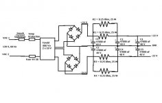
The last schematic looks very good.
>one PSU per monoblock
Nice.
I suppose a dual bridge design eases the strain on the
rectification stage?
Exactly.
>24 V out of the bridge then a drop to 22V
With 24V (give or take) from the bridge and a 5A load per rail,
the parallel 0,25 Ohm i.e. 0,125Ohm will drop 0,625V.
This is no problem whatsoever if you aim at 22V nominal for a
power amplifier. Remember, I do not know what bridges you use.
They could drop anything from 1 to 2,5V depending on type.
Also Rinternal for the transformer will drop anything from 0,5 to 1V.
Factor in 120V primary +/- 10% and your millage may vary.
So a nominal 22V could be anything from 20 something up to
23 something and your PSU will be perfect for an Aleph-X.
I would not want to go lower than 20V per rail.
>I was hoping that the filter would make...... ripple issue.
I agree, at nearly 150mF per rail ripple will not be an issue.
I guess you can start breadboarding and testing the supply.
A variac is a handy tool when doing this, and i hope you can
borrow / buy / use one.
Regards
Adding bypass
You can add bypasses (i have used some PIO caps succesfully), snubbers etc.......
As long as you are very carefull not to introduce any unwanted
resonances or other nasty things. If you have a oscilloscope,
a spectrum analyzer and a little knowledge... you can tweak the
PSU all you like.
You can add bypasses (i have used some PIO caps succesfully), snubbers etc.......
As long as you are very carefull not to introduce any unwanted
resonances or other nasty things. If you have a oscilloscope,
a spectrum analyzer and a little knowledge... you can tweak the
PSU all you like.
rtirion,
Thanks for all your help. We purchased the toroids this week from Antek at a great price (part number 8218 at $85 a piece). We've been doing a lot of reading on slew rates and impedance while we decide what components to buy.
Just for anyone else who may be using this link in the future for PSU design, read these:
http://www.tnt-audio.com/clinica/ssps1_e.html
http://www.analog.com/library/analogDialogue/Anniversary/21.html
the first link being REALLY helpful.
Thanks again for all of your help. We may just order parts for one PSU and see if we have a good unit. We'll keep you posted on our findings!!!
Jeff...
Ted,
We are open to suggestions if it will not greatly complicate the design. I was encouraged to read the following (in a filtering discussion):
"Large reservoir capacitors notwithstanding, for really high quality
power supply we need additional filtering. As seen on the Diagrams,
small value capacitors, in the 100-220nF region are used to filter out
the very high frequencies, where large capacitor efficiency has
already dropped to unacceptable levels. This is no big deal, you can't
really go wrong here whatever you do - the only way to go wrong is not
to do it, and even that may not be critical, depending on actual
circuit layout (if your large filter caps are next to the output
transistors, for example, the effects will be smaller, but they will
still be there) "
link to above discussion:
http://www.tnt-audio.com/clinica/ssps1_e.html
It almost sounds like we just need to throw some in there. Would you mind marking up our schematic with some suggestions???
Jeff...
Just picked up a monster 4'x8.5' sheet of 3/16" Aluminum, with a small corner missing. Guy was gonna scrap it, and gladly took $85 for it.
Gonna try and copy the heat sink design from this guy:
http://www.diyaudio.com/forums/showthread.php?&threadid=73543
I'm thinking this will leave me a wide margin so I can up the bias.
 Yeah! Yeah! Yeah!
Gonna try and copy the heat sink design from this guy:
http://www.diyaudio.com/forums/showthread.php?&threadid=73543
I'm thinking this will leave me a wide margin so I can up the bias.
Yeah! Yeah! Yeah! Gentlemen,
"This guy" has been lurking here. As well as a general word of encouragement I would like to add a couple of comments.
1) The 3/16" Al sheet based heat sink I used works well primarily because I spread the heat generation out. If you google you'll find sources that will give equations for calculating heat dissipation efficiencies of Al plates. I used 20 output transistors each dissipating 13W. I found that I was able to increase the dissipation to 15W each with no problem. However, the heat gradient is high. This means that most of the heat is dissipated by the Al close to the transistors. In my case I felt that the edges of the plates weren't adding much to the effectiveness of the sink.
With 12 output transistors per channel, 22V rails, and assuming around 5A of total bias, I estimate the dissipation of each transistor to be about 17W. I would keep my eye on this but you should be OK.
2) The AX100 thread also includes a good description of the power supply I used.
3) I am curious about the load you're intending to drive. With 22V rails you won't be able to put 100W into 8 ohms. I would expect you to get more like about 75 watts. Taking this into consideration you could reduce your total bias to 4.5 amps and still get your 75W but you would reduce the heat produced by each transistor to about 15.4W. Just a thought.
Good luck with your project. The Aleph-X remains one of the best DIY amps on the planet.
Cheers,
Graeme
Thanks for the feedback gl (aka "This Guy"). I am surprised to hear you have a "high" heat gradient for you transistors. How did you fixed/mounted the transistor to the Al plates? I recently read an article:
http://sound.westhost.com/heatsinks.htm
that reinforces the importance of mounting. The ol' weakest link theory comes to mind here.
To aid us in heat transfer we will be using plates with a larger surface area to account for the higher heat dissipation (per transistor) needed in our design. Although we haven't made a final decision yet, we will probably have double the surface area per transistor in our final enclosure design (compared to yours). We want to play the Russian Roulette Bias Game - how high can you go???
The PSU experience continues...
Now that we have a good schematic we have started looking into what components we will be purchasing. From looking within the forum it seems as though there was a lot of discussion about good parts to use in the year 2002 and then a revisit in 2004. Based on what we have read from posts, several years ago, I can sum it up by the following:
1. There was some debate over High Speed vs. Schottky Diodes (2002)
2. It appears that there was concern over Schottky diodes not being robust/reliable enough, but were typically consider the better choice. (2002)
3. Nelson Pass said said "I think you can find some 50 volt Schottky diodes, and IMHO they represent the absolute best." (2002)
4. The Schottky diodes became more advanced (in 2004) and eliminated the material lead from them. This allowed the RoHs compliant exclusion to be lifted and mandated RoHS Shottkys to not have lead in them
5. Schottky diode packages became more advanced having terminal screw lugs integrated into them (http://www.diyaudio.com/forums/showthread.php?s=&threadid=28497&highlight=) (2004)
6. It is widely accepted that some margin of headroom should be made for the bridge diodes; sometimes as much as 6 times the anticipated voltage. However Nelson pass says that "Some margin is generally built into the manufacturer's spec, so a 50 V rectifier exposed to 51 volts is not likely to be a problem." (2004)
My question is what about the year 2008??? I am sure there are better, choices now then back in 2004 and 2002.
Are these statements still relevant and correct given the advancement of Schottky (or other) diodes today?
Right now we are considering a Schottky rectifying bridge that has been around for some time:
http://www.mouser.com/Search/Refine.aspx?Keyword=625-mbr1045
We are also looking into:
http://www.mouser.com/Search/Refine.aspx?Keyword=HFA08TA60C
but aren't sure these will meet our needs.
Does anyone have a more modern recommendation for us? It seems like we should be able to find a more up-to-date bridge that would have better performance than what was used several years ago.
Jeff...
- Status
- This old topic is closed. If you want to reopen this topic, contact a moderator using the "Report Post" button.
- Home
- Amplifiers
- Pass Labs
- Hi powered Aleph-X PS