Hi guys,
I soldered back old resistors, some of them are 3 bands some 5 bands which my DM can't even measure the ohms on them. All I left is one 100ohm fuse resistor that was blown for sure. My hi-fi ticked and I get sound from R speaker! Still no sound form L speaker . I need to do more debugging.
I soldered back old resistors, some of them are 3 bands some 5 bands which my DM can't even measure the ohms on them. All I left is one 100ohm fuse resistor that was blown for sure. My hi-fi ticked and I get sound from R speaker! Still no sound form L speaker
. I need to do more debugging.Pin 16 is good, -54.1v. I've noticed that those weird 3-5 band resistors were actually a capacitors .
New data with R speaker working.
STK4231II IC:
Pin 1 : +52.0v
Pin 2 : +51.6v
Pin 3 : -0.201v
Pin 4 : -0.205v
Pin 5 : -0.003v
Pin 6 : -50.1v
Pin 7 : +50.5v
Pin 8 : +2.998v
Pin 9 : -52.5v
Pin 10 : -53.3v
Pin 11 : -54.2v
Pin 12 : -0.061v
Pin 13 : +54.1v
Pin 14 : +53.2v
Pin 15 : -0.133v
Pin 16 : -54.1v
Pin 17 : -0.003v
Something is not right with pin 7 and 8. I'm unable to measure pin 20. @Mooly, there's no physical damage on the transistor, but I'm not certain if it's good. Pin 7 is connected to a 4.7K ohm resistor that measured +50.5v with unit powered on. Which pins are for L speaker?
.New data with R speaker working.
STK4231II IC:
Pin 1 : +52.0v
Pin 2 : +51.6v
Pin 3 : -0.201v
Pin 4 : -0.205v
Pin 5 : -0.003v
Pin 6 : -50.1v
Pin 7 : +50.5v
Pin 8 : +2.998v
Pin 9 : -52.5v
Pin 10 : -53.3v
Pin 11 : -54.2v
Pin 12 : -0.061v
Pin 13 : +54.1v
Pin 14 : +53.2v
Pin 15 : -0.133v
Pin 16 : -54.1v
Pin 17 : -0.003v
Something is not right with pin 7 and 8. I'm unable to measure pin 20. @Mooly, there's no physical damage on the transistor, but I'm not certain if it's good. Pin 7 is connected to a 4.7K ohm resistor that measured +50.5v with unit powered on. Which pins are for L speaker?
Hi,
You are confusing me now Pin 8. That's the muting input and is common to both channels so if one side works there is no problem there.
Your voltage readings don't make sense, well they do, but that points to the STK again. The output is pin 12, and that should be around zero, pin 7 should be around a couple of volts negative.
How have you got one channel to work ? Does the relay pull in now, or have you bypassed it and connected the speaker to the amp directly.
The transistor -- what type is it, is it the same as the other one that I can see in the picture ? Swap them over ?
You are confusing me now
Pin 8. That's the muting input and is common to both channels so if one side works there is no problem there.Your voltage readings don't make sense, well they do, but that points to the STK again. The output is pin 12, and that should be around zero, pin 7 should be around a couple of volts negative.
How have you got one channel to work ? Does the relay pull in now, or have you bypassed it and connected the speaker to the amp directly.
The transistor -- what type is it, is it the same as the other one that I can see in the picture ? Swap them over ?
Attachments
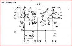
Best not to have the speakers connected while troubleshooting. To avoid frying them and because that can hide what circuit nodes are doing. For instance, pins 12 and 15 should go very close to 0 volts all by themselves, without the speaker tugging them down there. Connecting to speakers and listening for sound is not a good first check to see whether a power amp has been fixed -- make sure it can make the output DC go to zero on its own, first.
Pins 7 and 17 should have pretty much the same voltages on them (with the volume control turned all the way down).
Pin 7 and pin 2 being near +50V makes no sense at all if pin 12 is 0v and the STK amp is still alive on that channel (so it probably isn't). Pin 12 should sit at about 1.5V below pin 2, cant be 50V below it and the module still usable. Make sure you measure with the volume control down, no audio feeding it (and the speakers disconnected). You have to get DC right before worrying about AC (audio).
I'm pretty sure R11 (resistor that connects to Pin7) is burned open. If not, R20 is, and C15 is getting ready to explode. Or pin voltages aren't being read correctly. (the R and C numbers are per the example circuit on the data sheet, not on your amp board, we don't know what they're called there).
Mooly -- If I'm reading schematic and spec sheet right, a negative voltage on Pin 8 should cause muting, a positive one should unmute. So the one channel playing (the Pin 15 side) makes sense. Like you say, though, the Pin 12 side appears to be fried. Or pin 12 isn't soldered to the board or something like that.
Pin 8. That sounds right. The measurements show 3 volts, and that gives audio on one channel.
Pin 7 is the " return " end, if that's what you call it, of the voltage amplifier stage or VAS. 50 volts here isn't right. Are those 4k7 OK ?
It is getting difficult to analyse because parts have ( I think from what you say ) been removed and replaced without you even being 100 % sure what they are. Can we be 100 % sure all the bits are where they are meant to be. It has to be something really simple this.
A 47uF 50v cap (C857) exploded on me, it is connected to Pin 7 and 4.7K resistor:
^ That's the best my webcam can do. I moved few parts to the backsite of the pcb. Notice that first 2 and last 2 pins of the STK don't even have traces on the pcb. @Mooly, I plugged in my speaker to R channel, I will take greater care next time to avoid any damage. I have spare 4.7K resistors so I will replace those, last time I checked them out of the circuit they were fine.
An externally hosted image should be here but it was not working when we last tested it.
An externally hosted image should be here but it was not working when we last tested it.
^ That's the best my webcam can do. I moved few parts to the backsite of the pcb. Notice that first 2 and last 2 pins of the STK don't even have traces on the pcb. @Mooly, I plugged in my speaker to R channel, I will take greater care next time to avoid any damage. I have spare 4.7K resistors so I will replace those, last time I checked them out of the circuit they were fine.
nfm-
You should be able to measure the resistance between pins 6 an 7 with the 4.7ks still in there (try with probes both ways, transistor junctions can affect readings in one of the directions). If you can measure resistance higher than about 10k ohms (the two 4.7k in series) either way, find what's missing.
Or removing them and measuring them is ok, too, just more work. Definitely a problem around there (especially if the 47uF blew up), or else those two resistors must be getting hot. But sadly fixing that problem still isn't likely to make that channel work, the voltages you gave before indicate that the STK is blown on that side.
The disconnected pins 1,2,21,22 are on the module for adding compensation C (can make amp more stable, but hurts slew rate), it's not unusual that they aren't used here.
kinda fun trying to do this "by keyboard" as Mooley said. A challenge but someone else gets to do all the physical work!
9.36k ohms between pin 6 and 7. Those resistors get warm, I wonder if it's the STK leaking the voltage, and I'm also wondering if old STK survived, but it's a pain to solder it back because the legs need to be straightened out & properly bend in u-shape so it fits the heatsink at a proper height.
Sad sad... .
.
Sad sad...
.This probably sounds drastic but as you are stuggling why not remove the STK. Then check and double check each resistor on that PCB. Use solder braid to isolate one leg so you get a true reading. Then check each and every cap, it's value, it's polarity.
Unsolder two of the legs on those transistors and compare reading one to another. Check any small diodes. Check your soldering, no little whiskers shorting anything out ?
It's not the ideal way to fault find but unless you understand the theory and why incorrect voltages are appearing and how to interpret those readings you are not going to fix this easily.
This isn't easy at the end of a keyboard.
I would try comparing one channel against the other, and it may be worth seeing if the other channel actually works OK. That means taking the output from pin 15 to a speaker, not directly, maybe through a 100 ohm to begin with, or a cap to protect it if anything happens. Assuming thats OK it should be possible to compare then.
So i came across this thread as i had the same problem with my garage stereo. It turns on, but the relay won't kick over. I followed the thread through, and have a few questions.
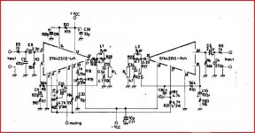
First of all, my amp is a different model, but very similar it is a st4221II
here is the diagram
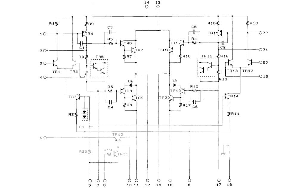
here are my readings at the pins when energized
1= 46
2=47
3=0
4=7
5=0
6=-50
7=50
8=3
9=-53
10=-53
11=-54
12=54
13=54
14=46
15=2
16=-54
17=44
18=0
19=2
20=0
21=47
22=47
SO i tried what was quoted above, wiring the speaker directly to pin 15, and the speaker worked but it was very quiet, and it could not be adjusted. what does this tell me? Does that mean my amp is cooked? both not producing enough power, and shorting out somewhere causing the protection to block power to the relay?
Or is there something after the amp that controls volume, and is the fault somewhere in between either pin 15 or 12 and the relay?
any help/advise would be appreciated.
good point, i just tried it on 15, as the voltage was low. if i disconnect the other channel (pin 12) my relay should in theory kick on, if all other components are in working order.
I have 53 volts across the relay, and both contacts are open. one contact is holding 2 vdc, and the other 53. so prtoection is telling it to hold both contacts open?
I have 53 volts across the relay, and both contacts are open. one contact is holding 2 vdc, and the other 53. so prtoection is telling it to hold both contacts open?
so I interrupted voltage coming from pin 12, and the relay kicks over. but the sound coming from the speakers is still nothing more than a whisper. is the voltage in pin 12 suggesting that the amp is shorted on one channel, and the voltage in pin 15 suggesting that the second channel is just to weak to produce and sound?
- Status
- This old topic is closed. If you want to reopen this topic, contact a moderator using the "Report Post" button.
- Home
- Design & Build
- Parts
- Hi-Fi Stereo went BOOM