Hello, can I design a portable headphone amp runing on 5- 12v with these hexfet's ? http://skory.gylcomp.hu/alkatresz/irf7319.pdf
Maybe an op amp driving them ?
They are out of an DVD 5.1 , 2pairs for one output , with some weird Ic's before them 3state buffer sop20 ( fairchild P27AB MM74HC )
I only want to use the HEXFET'S
Maybe an op amp driving them ?
They are out of an DVD 5.1 , 2pairs for one output , with some weird Ic's before them 3state buffer sop20 ( fairchild P27AB MM74HC )
I only want to use the HEXFET'S
Gate/Source threshold is the point at which the FET begins to come into conduction. The data sheet quotes 250uA at that point, which won't get you very far driving headphones ")
Nothing happens below that voltage point, and to turn it fully on requires as much as 5 volts, and you can go even higher than that to squeeze the last drop of 'conductivity' out of it.
They just wouldn't be my first choice given you mention going as low as a 5 volt supply as part of the design brief.
Don't let that stop you from experimenting though
I haven't use mosfets just once in a design , there was around 4v g-s it had some distortion. I dont really know how to bias them. In a push pull config , Headphone Amplifier Can i replace Q1 Q2 with these fet's , how do I calculate R5 /6 , vbe multiplier instead of D1 D2 maybe ..
It would not be straightforward. The supply voltage (-/+15) is fine but the whole bias network is totally inappropriate for FET's. D1 and D2 would have to be replaced by something generating a higher voltage... you might get lucky and a combination of series diodes or diode and zener or even LED got you the desired current, or you might have to design an adjustable multiplier to give fine control over the bias setting. At least the 10 ohm resistors should keep any thermal effects in reasonable check.
Use a DC-DC step up converter and run them at circa 18v to 24v and they should work well. You could use any number of SE Class A designs available here or even push pull designs like an F5 topology. One intersting thing to try is to have the N-channel set up as a CCS and the P-channel as the output stage in a SE Class A. It would be very compact.
Heat removal might be an issue with such a tiny package - maybe metal core SMT PCB's?
I have used these - they work really well and noise free if passed through a simple CRC filter:
DC DC boost converter Constant Current Mobile Power supply 10A 250W LED Driver-in Integrated Circuits from Electronic Components & Supplies on Aliexpress.com | Alibaba Group
Yes, they need 4V drive... for 20 Amps flow!! We don't need to hit them that hard. Headphones don't need even 300mA, 0.3A.
The 1V @ 250uA is not directly useful, no. But this and the 4V @ 20A define a curve that we want to find mid-points on.
The total range 250uA to 20A crosses at least two MOSFET modes, and we can't know the exact curve of the line. But it will be roughly straight, with a bend, plotted on the log/lin paper the spec-sheet uses. I've attached my guess. I think the headphone current range is 1.5V-2V. This is very approximate, and the bias MUST be tuned to the actual devices.
This is not a "bad" voltage for a 12V headphone amp. However the next question is to fill in the rest of the plan. Which is really a request to give free design services so that some very specific "free" MOSFETs can be used. Which is considerable thinking time, and more time to write/draw it up.
Attachments
If I can't really use these hexfet's , easiest way would be to use some op amp + BD139-140 by rod elliot's headphone amp schematic on + - 2.5v , 0.6v for the transistors , would I get at least 1v - 1.5v output on 5v supply ?
Since my phone/ mp3 player doesnt have the "omph" for my headphones ( 32ohm ) I want a small portable headphone amp ( 5v would be great as I have one external battery 5v 2amp output ( 6amp capacity )
Since my phone/ mp3 player doesnt have the "omph" for my headphones ( 32ohm ) I want a small portable headphone amp ( 5v would be great as I have one external battery 5v 2amp output ( 6amp capacity )
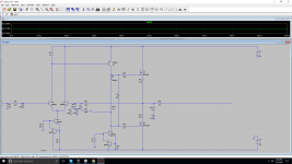
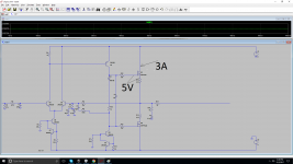
Weird thing , I've tired some schematics in LTSpice to " play " with mosfets, see their Vgs , how much to open them, etc. Every mosfet even at 4 - 6v Vgs it draws a few 5-10 - 30 amps from the rails, this is weird .
Even this one only with one 1n4148 across gates I get 11v Vgs and 88A from rails. Even with 4-0-4 V RAILS I get 3amps .. Something wrong with my LTSpice maybe...?
Even this one only with one 1n4148 across gates I get 11v Vgs and 88A from rails. Even with 4-0-4 V RAILS I get 3amps .. Something wrong with my LTSpice maybe...?
Attachments
Your 5 volt requirement is the killer for all these.
Why not have a look at something like the TDA2822 chip which operates down to a couple of volts. Fig 1 in the data sheet is all that is needed. Add a volume control and possibly a low value series feed resistor to the headphones and your done.
http://www.st.com/content/ccc/resou...df/jcr:content/translations/en.CD00000134.pdf
- Status
- This old topic is closed. If you want to reopen this topic, contact a moderator using the "Report Post" button.
- Home
- Amplifiers
- Headphone Systems
- HEXFET headphone amp !?