Add paraffin oil, pumice or rottenstone and a pad. Instead of 0000 steel wool. You are now "French Polishing." You just have to get the padding technique right. All the pores will be sealed and you will have a mirror finish. You can also save yourself some work by getting the commercially prepared "French Polishes" Concocting your own mixture of oil, shellac and denatured alcohol is the tricky part.
Don't sand your shellac off.
Don't sand your shellac off.
There is a design using an omni reflector on the German Hi-Fi Sound site here. The project isn't described on the English part of the site so you may have to go via Babel or Google for a translation - which is always entertaining in its own right!
The actual diffuser is described in more detail here.
Hope this provides some inspiration.
The actual diffuser is described in more detail here.
Hope this provides some inspiration.
Hi John,
I don't know if this will help, but when I did my omni project with diffuser/horns similar to the Duevel Venus, I created a cad drawing of the diffuser profile. I did it by finding the best examples I could in photos of their diffusers in profile, referenced them into the cad drawing and traced them. Then I scaled them to meet the size I wanted to use.
Attached is a pdf of that file. If it is the correct size for what you want, you can print it out at the pdf scale on an 8.5"x11" paper and it should scale at 1/4" = 1".
Attachments
John L said:
After I have sanded the base pieces, I will seal them with my good old shellac,
Not sure what I should use. Any suggestions?
Tough break on the veneer, but the results look good.
Ideas on painting something black: I'm trying a different approach in this thread.
Probably won't suit you (doesn't involve shellac
), but a suggestion anyway.MJL21193 said:
Tough break on the veneer, but the results look good.
Ideas on painting something black: I'm trying a different approach in this thread.
Probably won't suit you (doesn't involve shellac
I like your approach. I am going to ask you a question you probably wrote about earlier, but I did not know your project existed until just now. How did you spray on your urathane sealer? Did you use a can or spray gun?
And I like what you have done there. It's a great idea.
In my case I will only be using the shellac as a sealer, before applying the paint. Can't make up my mind what I want to use. Using a laquer is so time consuming in that the surface must be perfect before application, and then the process of rubbing down the uneven build-up takes forever, it seems. There is a word for that uneven build up but I have forgotten off the top of my head.
What would you suggest?
PS: your project is stunning! I'll make a point of reading it from start to finish as soon as I can. I'll try to add to it in order to keep things lively there. Always pays to keep the thread going.
dlneubec said:Hi John,
I don't know if this will help, but when I did my omni project with diffuser/horns similar to the Duevel Venus, I created a cad drawing of the diffuser profile. I did it by finding the best examples I could in photos of their diffusers in profile, referenced them into the cad drawing and traced them. Then I scaled them to meet the size I wanted to use.
Attached is a pdf of that file. If it is the correct size for what you want, you can print it out at the pdf scale on an 8.5"x11" paper and it should scale at 1/4" = 1".
Dan, thanks so much for the PDF containing the diffuser drawing. Mine were pretty much like yours, with only one exception, which can possibly make a Real difference. With mine, the entire top half is curved in a convex shape. Since my day class on the lathe Saturday, I have realized that turning the concave surface is more than twice as easy, compared to the convex shape.
With your drawing, the upper section is pretty much a straight line, until it reaches the top, when it then becomes a convex shape. Your shape would be far easier to turn, I believe. I'll make up several blanks and when I attend my next class I will try both types. Fortunately, the bottom concave shape will be perfect for either style.
Again, thanks for the revelation. I appreciate it. Any more help is more than appreciated.
John L said:
How did you spray on your urathane sealer? Did you use a can or spray gun?
What would you suggest?
Hi John,
Thanks for your kind comments.
On the main speakers I sprayed everything - with a real paint sprayer. Spray cans IMO are only useful for very small things.
With the centre speaker I'm currently working on, I'm trying a different method. I rolled on two coats of clear polyurethane as the sealer. MDF swells at the slightest hint of water, so putting my waterbased finish directly on it would have caused problems.
I can't say enough good things about the paint I'm using - it's fantastic. Tough as nails, fast drying, water clean-up, non toxic, the whole shebang. A little bit expensive, but well worth twice the price.
MJL21193 said:
I can't say enough good things about the paint I'm using - it's fantastic. Tough as nails, fast drying, water clean-up, non toxic, the whole shebang. A little bit expensive, but well worth twice the price.
Can you describe it more? I'm interested in the brand and type. A good roll on seems too good to be true. I've always had to spray on for a fine finish.
Data sheet here. I talk about it a bit here.
Don't get me wrong, the results that are possible with a roller do not compare to a good spray finish. That I will be applying the paint then colour sanding is what will make it acceptable.
Don't get me wrong, the results that are possible with a roller do not compare to a good spray finish. That I will be applying the paint then colour sanding is what will make it acceptable.
John L said:
Dan, thanks so much for the PDF containing the diffuser drawing. Mine were pretty much like yours, with only one exception, which can possibly make a Real difference. With mine, the entire top half is curved in a convex shape. Since my day class on the lathe Saturday, I have realized that turning the concave surface is more than twice as easy, compared to the convex shape.
With your drawing, the upper section is pretty much a straight line, until it reaches the top, when it then becomes a convex shape. Your shape would be far easier to turn, I believe. I'll make up several blanks and when I attend my next class I will try both types. Fortunately, the bottom concave shape will be perfect for either style.
Again, thanks for the revelation. I appreciate it. Any more help is more than appreciated.
I'm not clear on what your plans are. Are you needing a top diffuser, or is it simply for looks? I included it because that was the shape and configuration used on the Venus, but I thought you were mounting the tweeter in the woofer center so it was up firing into the concave cone.
I tested the convex top diffuser (Venus) shape with a Seas27TDFC, downfiring and it had a terrible measured response. I have had much better looking frequency response results from the concave cone shapes and would recommend that profile over a convex curved surface for tweeters as wel as mids or woofers, based upon my testing.
Dan, I really need to scan some of my drawings into the computer and post them here, because nobody has any detailed idea as to what I am planning.
And you are right, the tweeter is going to be mounted on a phase plug, with both firing upward into the diffuser. The top is going to be rounded for asthetic purposes and will need to be rounder than with the Venus. Having it more pointed is useless because the tweeter is not going to be placed there.
Unfortunately, a completely rounded top is more difficult to turn on the lathe. Naturally straight lines and concave cuttings are easier. With straight lines you only need to set up the tool rest to follow the straight line, set your hand properly, and then glide across the rest as you cut the turning. With the Concave cut, you do not need to move your hand as much, but rather turn your wrist to round the cutting.
With a convex shape, the movement of your hand is much more complex, requiring you to not only move your wrists, but your entire hand, and pivoting your body is less important. It is probably four to ten times more difficult to make a convex cut. So, the less of it I am forced to do, the easier it is for me to get a nice looking diffuser.
If you go back to your pdf, and look at the top piece, the upper sides are not rounded, but more straight. In fact they are sligltly concave, and that would have to be changed. but the top is going to have to be convex, and the less this area, the easier to turn the upper section.
Before I took that day class Saturday, I had no idea just how difficult it is to use the different tools, round corners, and actually cut into the work, rather than scraping it off. There is a big difference, and a sharp cutting tool, will produce a finish that requires less sanding the better the cut.
I really need to say something about my class, but I forgot to carry along my camera. I promise you that I will carry it the next time I go. And I will take many pictures too.
Incidentially, do you have pictures of your project where you use the diffuser? Do you have any pictures of your cabinets?
Re: woodturning
Ok. Thanks Ed.
Ed LaFontaine said:John,
You may already know this: ask your instructor to demonstrate shear-scraping. It is great to improve the surface and decrease sanding.
Ok. Thanks Ed.
John L said:Incidentially, do you have pictures of your project where you use the diffuser? Do you have any pictures of your cabinets?
Hi John,
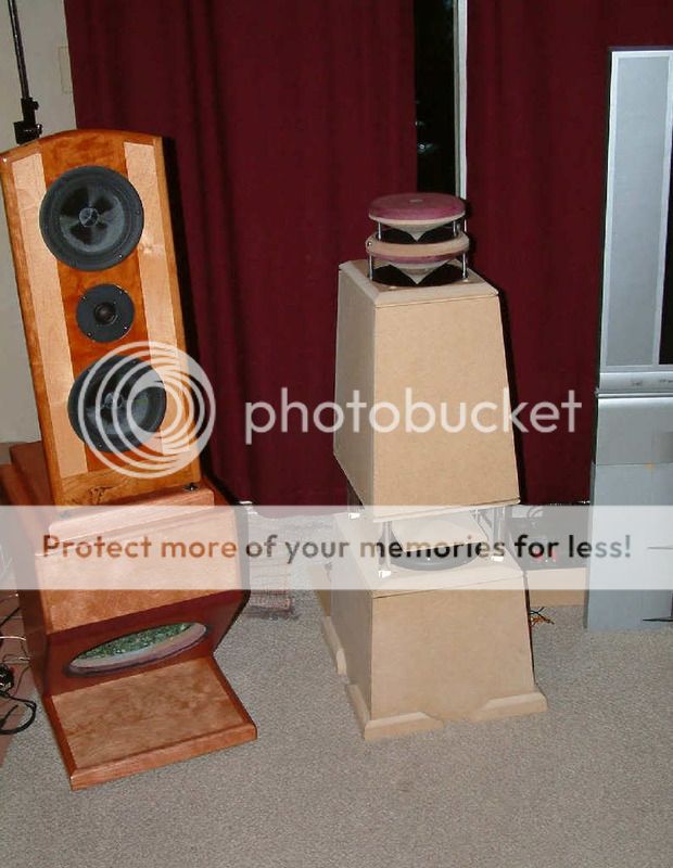
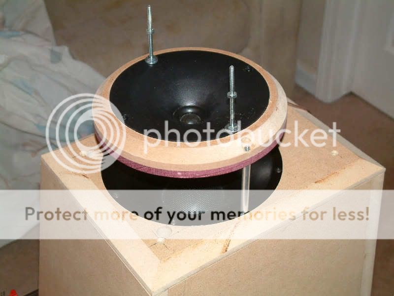
This was for the waveguide omni that I posted a link to. The lower diffuser was cut down in diameter to about 8.5" from the design in the pdf I posted. By way of explanation, it has an up firing 2" dome mid into the lower diffuser, which houses a 3/4" dome tweeter, which fires up into a second diffuser. Both the dome mid and the tweeter are mounted in waveguides, creating a true horn effect. Here are a couple of photos:
Here is what I have in mind for the diffuser horn. Since I am not knowledgable with drawing programs, I had to hand draw, scan, and upload it to my pic site.
The drawing at the top is pretty much like how I will make this first setup for the project. Since I am creating a coaxial, in which the tweeter is set up on the end of a phase plug, and both the driver and tweeter situated at the top of the cabinets, firing upward, there is no need to do anything but round off the top.
And this may be too rounded, and needing to be flattened a little bit more.
The bottom drawing is what I have in mind for the next project, in which a high compression horn/tweeter can be fit into a cavity drilled out of the bottom portion of the horn assembly, and fired upward into another diffuser, that conformes to the general shape.
Anyway, if anyone has more suggestions, please feel free.
Each of the two diffusers will be turned from two seperate blanks, with the two turned and then glued together to form one single diffuser.
With the bottom one, the top portion will have a horn effect lathed into it so a lense horn can be screwed to the diffuser and be a one piece assembly. By the time I finally get around to this example, I will probably have modified it make it more efficient. For instance the little top diffuser may well be wider and set up higher, out of the plane of the curve in order to gain a wider dispersion
An externally hosted image should be here but it was not working when we last tested it.
The drawing at the top is pretty much like how I will make this first setup for the project. Since I am creating a coaxial, in which the tweeter is set up on the end of a phase plug, and both the driver and tweeter situated at the top of the cabinets, firing upward, there is no need to do anything but round off the top.
And this may be too rounded, and needing to be flattened a little bit more.
The bottom drawing is what I have in mind for the next project, in which a high compression horn/tweeter can be fit into a cavity drilled out of the bottom portion of the horn assembly, and fired upward into another diffuser, that conformes to the general shape.
Anyway, if anyone has more suggestions, please feel free.
Each of the two diffusers will be turned from two seperate blanks, with the two turned and then glued together to form one single diffuser.
With the bottom one, the top portion will have a horn effect lathed into it so a lense horn can be screwed to the diffuser and be a one piece assembly. By the time I finally get around to this example, I will probably have modified it make it more efficient. For instance the little top diffuser may well be wider and set up higher, out of the plane of the curve in order to gain a wider dispersion
John L said:Dan, is this the project in which you had less than stellar results?
Yes, it never went beyond the prototype you see, because it simply was not as good as the other hybrid omni designs in side by side listening tests.
Based on my expereince, having a direct firing driver in the upper frequencies, tends to give you better imaging and might have less room reflection issues.
dlneubec said:
Yes, it never went beyond the prototype you see, because it simply was not as good as the other hybrid omni designs in side by side listening tests.
Based on my expereince, having a direct firing driver in the upper frequencies, tends to give you better imaging and might have less room reflection issues.
There are probably some ways to get around this. First, the diffuser will have to be large, and curved enough to allow the high frequencies to be dispersed around the room at a lower level, more where the person is sitting.
And second a more efficient compression horn will tend to work better than just a high efficiency tweeter. If you look at all three models Duevel use, they are all high compression horns. HC horns are almost always far more efficient than other tweeters, and should be far better at taking up the slack.
That's just my guess, of course.
Incidentially, that must be the reason why you have that PE tweet facing front and center in your new project.
Dan, I noticed only two posts holding things up... even if it feels sturdy it'll be bad on a smaller scale, vibrations will smear the driver's output. It takes three points to create a plane. keep it in mind for future reference.
Looks neat; even if it didn't work out for you, I bet it was fun to make. We learn more from failures anyway. Your subsequent stuff looks great.
Looks neat; even if it didn't work out for you, I bet it was fun to make. We learn more from failures anyway. Your subsequent stuff looks great.
Hi Bartek,
I agree with you, especially where a driver is physically attached. In this case the lower diffuser is held up on 3 posts, the third being directly behind in the middle and out of site. This diffuser also holds the tweeter. The top diffuser is held up with only two posts, but serves as a diffuser only and for frequecnies above about 3.5khz. Still, it might have been better with posts. The tweeter, however, sounded pretty good.
I think the main problem with the design was mostly due to the metal mid dome, combined with the plastic waveguide and firing into a diffuser. I lined the waveguide with plumbers putty in order to kill any resonances, but it never sounded right in the midrange, though it measured quite flat. I suspect that the mid dome would have probably sounded better with more room to breath. The design may have been better with a cone midrange or with fuller range midwoofer. I took the prototype to a DIY meet in Indiana and a lot of guys actually thought it was great, but I was never happy with it.
- Status
- This old topic is closed. If you want to reopen this topic, contact a moderator using the "Report Post" button.
- Home
- Loudspeakers
- Full Range
- Hexagon Pioneer B20FU20 Enclosure